Micromachined optical switching devices

a micro-machined, optical switching technology, applied in optics, instruments, electrical equipment, etc., can solve the problems of slow switching speed bulky macro-scale optomechanical switches, and extensive manual assembly of macro-scale optomechanical switches

Inactive Publication Date: 2002-09-03
CROSSFIBER +1
View PDF116 Cites 39 Cited by
  • Summary
  • Abstract
  • Description
  • Claims
  • Application Information

AI Technical Summary

Problems solved by technology

However, one problem with this macro-scale optomechanical switch technology is that macro-scale optomechanical switches are bulky.
Another problem with this technology is that macro-scale optomechanical switches require extensive manual assembly.
Another problem with this technology is that the switching speed of macro-scale optomechanical switches is slow.
An even more serious problem is that their switching times often depends on their specific switching path (i.e., how far is the distance from the next output port from the current output port).
This variation of switching time as a function of spatial displacement is highly undesirable from a systems integration point of view.
However, a problem with the anisotropic etching method is that monolithic integration of the micromirrors with the microactuators is difficult.
However, this is not a manufactur

Method used


Image

  • Micromachined optical switching devices
  • Micromachined optical switching devices
  • Micromachined optical switching devices

Examples


example

(5)

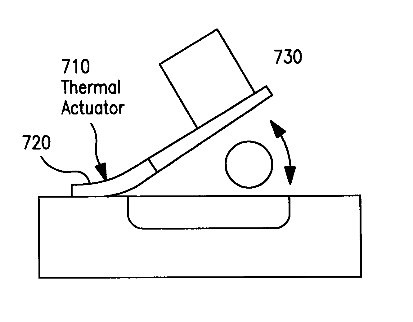
Another example includes a vertical mirrors on torsion plate configured to move with a push-pull electrostatic force. Thus, the torsion plate can be displaced with an electric field.

E. Matrix Switch Architecture for Uniform Fiber Coupling Loss

Most of the volume of an optomechanical matrix switch is composed of an array of free-space optical switches, an input fiber array, and an output fiber array. Such arrangement, however, has non-uniform optical insertion losses. In more detail, assuming the ends of the fiber are coplanar, the optical path length is different when each switching cell is activated (e.g., the optical path length of input #1 to output #1 is less than that of input #1 to output #8).

Referring to FIGS. 9A-9B, the invention includes an optomechanical matrix switch architecture that will have uniform optical coupling loss, independent of which switch is activated. A series of input fibers 910 are coupled to a substrate 920. An array of optomechanical switching cells 9...


PUM


Abstract

Various 3-port and 4-port micromachined optomechanical matrix switches are disclosed herein. In accordance with one aspect of the invention there is provided an optomechanical matrix switch including a substrate and a first plurality of optomechanical switching cells coupled thereto. Each of the first plurality of optomechanical switching cells is arranged to be in optical alignment with a first input port. A second plurality of optomechanical switching cells is also coupled to the substrate, each of the second plurality of optomechanical switching cells being in optical alignment with a second input port. In another aspect of the present invention an optomechanical matrix switch is provided which includes a substrate and a first plurality of optomechanical switching cells coupled thereto. Each of the first plurality of optomechanical switching cells is placed in optical alignment with one of a corresponding first plurality of input ports and with one of a corresponding first plurality of output ports. The matrix switch further includes a second plurality of optomechanical switching cells coupled to the substrate. Each of the second plurality of optomechanical switching cells is placed in optical alignment with one of a corresponding second plurality input ports and with one of a corresponding second plurality of output ports.

Description

1. Field of the InventionThe invention relates generally to the field of optical switching. More particularly, the invention relates to the design, fabrication, assembly and packaging of micro electro mechanical systems (MEMS) technology optomechanical switching cells, and N.times.M matrix switches composed thereof.2. Discussion of the Related ArtOptical switching plays a very important role in telecommunication networks, optical instrumentation, and optical signal processing systems. In telecommunication networks, fiber optic switches are used for network restoration, reconfiguration, and dynamic bandwidth allocation.There are many different types of optical switches. In terms of the switching mechanism, optical switches can be divided into two general categories.The first general category of optical switches employs a change of refractive index to perform optical switching. This first general category can be termed "electrooptic switches." Actually, the refractive index change can...

Claims


Application Information

Patent Timeline
IPC IPC(8): G02B26/08G02B6/35H04Q11/00
CPCG02B6/3514G02B26/0833G02B26/085H04Q11/0005G02B6/352G02B6/3546G02B6/357G02B6/3576H04Q2011/0026H04Q2011/003H04Q2011/0039H04Q2011/0049
Inventor FERNANDEZ, MARCHUSAIN, ANISFAN, LI
Owner CROSSFIBER
Why Eureka
Try Eureka