Optomechanical matrix switches including collimator arrays

a matrix switch and optomechanical technology, applied in the field of optical switching, can solve the problems of macro-scale optomechanical switches that require extensive manual assembly, macro-scale optomechanical switches are bulky, and the switching speed of macro-scale optomechanical switches is slow

Inactive Publication Date: 2002-09-03
CROSSFIBER +1
View PDF123 Cites 72 Cited by
  • Summary
  • Abstract
  • Description
  • Claims
  • Application Information

AI Technical Summary

Benefits of technology

An optomechanical switch made with micro electro mechanical systems technology offers significant advantages over conventional optomechanical switches for realizing optical crossbar switches. Since the surface area (footprint) of a micro electro mechanical systems fabricated switching cell is very small (e.g., from a few hundred micrometers to a few millimeters), an entire N.times.M switching matrix can be monolithically integrated on a single substrate (e.g., a single silicon integrated circuit chip). This significantly reduces the packaging cost of the switch. It also enables the entire switch to be hermetically packaged, which is a very important factor for the switch to satisfy the temperature and humidity requirements such as those in the Bellcore standard.The switching time can also be reduced because of their higher resonant frequency. The resonant frequency is proportional to the square root of the ratio of spring constant and mass. Switch cells fabricated in accordance with the invention can be much smaller (e.g., 10-100 smaller) physically than bulk mechanical switches. Consequently, switch cells fabricated in accordance with the invention can have smaller mass and, therefore, a higher resonant frequency. The higher resonant frequency is directly proportional to the speed of switching of the device. Furthermore, an optomechanical switch made with micro electro mechanical systems technology can be more rugged than the macro-scale switches because the inertial forces are much smaller in the micro-scale switches.All the disclosed embodiments of the invention described herein can be realized and practiced without undue experimentation. Although the best mode of carrying out the invention contemplated by the inventors is disclosed above, practice of the invention is not limited thereto. Accordingly, it will be appreciated by those skilled in the art that the invention may be practiced otherwise than as specifically described herein.For example, the individual components need not be formed in the disclosed shapes, or assembled in the disclosed configuration, but could be provided in virtually any shape, and assembled in virtually any configuration. Further, the individual components need not be fabricated from the disclosed materials, but could be fabricated from virtually any suitable materials. Further, although the N.times.M matrices are described herein as physically separate modules, it is understood that the matrices may be integrated into the apparatus with which they are associated. Furthermore, all the disclosed elements and feature of each disclosed embodiment can be combined with, or substituted for, the disclosed elements and features of every other disclosed embodiment except where such elements or features are mutually exclusive.It is understood that various additions, modifications and rearrangements of the features of the invention may be made without deviating from the spirit and scope of the underlying inventive concept. It is intended that the scope of the invention as defined by the appended claims and their equivalents cover all such additions, modifications, and rearrangements. The appended claims are not to be interpreted as including means-plus-function limitations, unless such a limitation is explicitly recited in a given claim using the phrase "means-for." Expedient embodiments of the invention are differentiated by the appended subclaims.

Problems solved by technology

However, one problem with this macro-scale optomechanical switch technology is that macro-scale optomechanical switches are bulky.
Another problem with this technology is that macro-scale optomechanical switches require extensive manual assembly.
Another problem with this technology is that the switching speed of macro-scale optomechanical switches is slow.
An even more serious problem is that their switching times often depends on their specific switching path (i.e., how far is the distance from the next output port from the current output port).
This variation of switching time as a function of spatial displacement is highly undesirable from a systems integration point of view.
However, a problem with the anisotropic etching method is that monolithic integration of the micromirrors with the microactuators is difficult.
However, this is not a manufacturable process.
However, a problem with the direct reactive ion etching method is that the surface of the etched sidewalls tend to be rough.
The actuators of DRIE mirrors are usually limited to comb drive actuators, which have a limited travel distance.
Referring to the third method, a problem with electroplated micromirrors is that they often may not have straight or vertical sidewalls.
The LIGA process can produce high quality micromirrors, however, it requires expensive X-ray lithography.
Further, integration with the actuators is a difficult issue for LIGA micromirrors.
This reduces the efficiency of the manufacturing process by significantly increasing the number of process steps.
In addition, control of the mirror angle to within 0.5.degree. as required by large matrix switches is difficult to achieve with microhinged mirrors and torsion micromirrors.

Method used


Image

  • Optomechanical matrix switches including collimator arrays
  • Optomechanical matrix switches including collimator arrays
  • Optomechanical matrix switches including collimator arrays

Examples


example

(5)

Another example includes a vertical mirrors on torsion plate configured to move with a push-pull electrostatic force. Thus, the torsion plate can be displaced with an electric field.

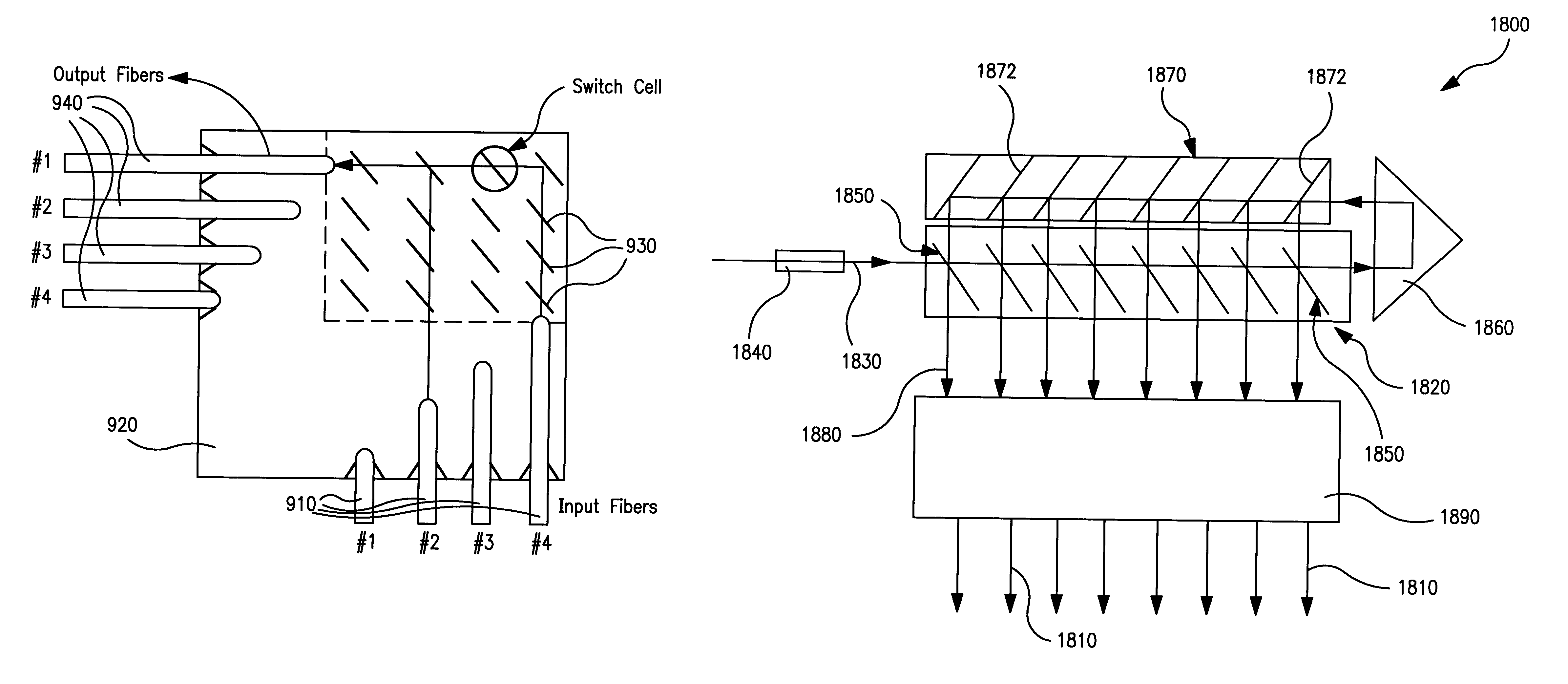
E. Matrix Switch Architecture for Uniform Fiber Coupling Loss

Most of the volume of an optomechanical matrix switch is composed of an array of free-space optical switches, an input fiber array, and an output fiber array. Such arrangement, however, has non-uniform optical insertion losses. In more detail, assuming the ends of the fiber are coplanar, the optical path length is different when each switching cell is activated (e.g., the optical path length of input #1 to output #1 is less than that of input #1 to output #8).

Referring to FIGS. 9A-9B, the invention includes an optomechanical matrix switch architecture that will have uniform optical coupling loss, independent of which switch is activated. A series of input fibers 910 are coupled to a substrate 920. An array of optomechanical switching cells 9...


PUM


Abstract

Various configurations of optomechanical matrix and broadcast switches are disclosed herein. One such optomechanical matrix switch includes a substrate and a plurality of optomechanical switching cells coupled thereto. Each of the optomechanical switching cells includes a mirror and an actuator. The matrix switch further includes an array of collimator elements, each of the collimator elements being in optical alignment with one of the optomechanical switching cells. Also disclosed herein is a distributed matrix switch including first and second optomechanical matrix switches. The first and second optomechanical matrix switches respectively include first and second pluralities of optomechanical switching cells mounted upon first and second substrates. A collimator array is interposed between the first and second matrix switches in optical alignment with the first and second pluralities of optomechanical switching cells.

Description

1. Field of the InventionThe invention relates generally to the field of optical switching. More particularly, the invention relates to the design, fabrication, assembly and packaging of micro electro mechanical systems (MEMS) technology optomechanical switching cells, and N.times.M matrix switches composed thereof.2. Discussion of the Related ArtOptical switching plays a very important role in telecommunication networks, optical instrumentation, and optical signal processing systems. In telecommunication networks, fiber optic switches are used for network restoration, reconfiguration, and dynamic bandwidth allocation.There are many different types of optical switches. In terms of the switching mechanism, optical switches can be divided into two general categories.The first general category of optical switches employs a change of refractive index to perform optical switching. This first general category can be termed "electro-optic switches." Actually, the refractive index change ca...

Claims


Application Information

Patent Timeline
Patent Type & Authority Patents(United States)
IPC IPC(8): G02B26/08G02B6/35H04Q11/00
CPCG02B6/3514G02B26/0833G02B26/085H04Q11/0005G02B6/352G02B6/3546G02B6/3556G02B6/357G02B6/3576H04Q2011/003H04Q2011/0049
Inventor GLOECKNER, STEFFENHUSAIN, ANISFAN, LI
Owner CROSSFIBER
Why Eureka
Try Eureka