
Captured synchronous DRAM fails in a working environment

a synchronous dram and working environment technology, applied in error detection/correction, instruments, computing, etc., can solve problems such as the inability of software to capture failures, the processing is too complex for software to control the hardware, and it takes months for product engineers to capture failures

Inactive Publication Date: 2002-10-15
GLOBALFOUNDRIES INC
View PDF17 Cites 65 Cited by
  • Summary
  • Abstract
  • Description
  • Claims
  • Application Information

AI Technical Summary

Benefits of technology

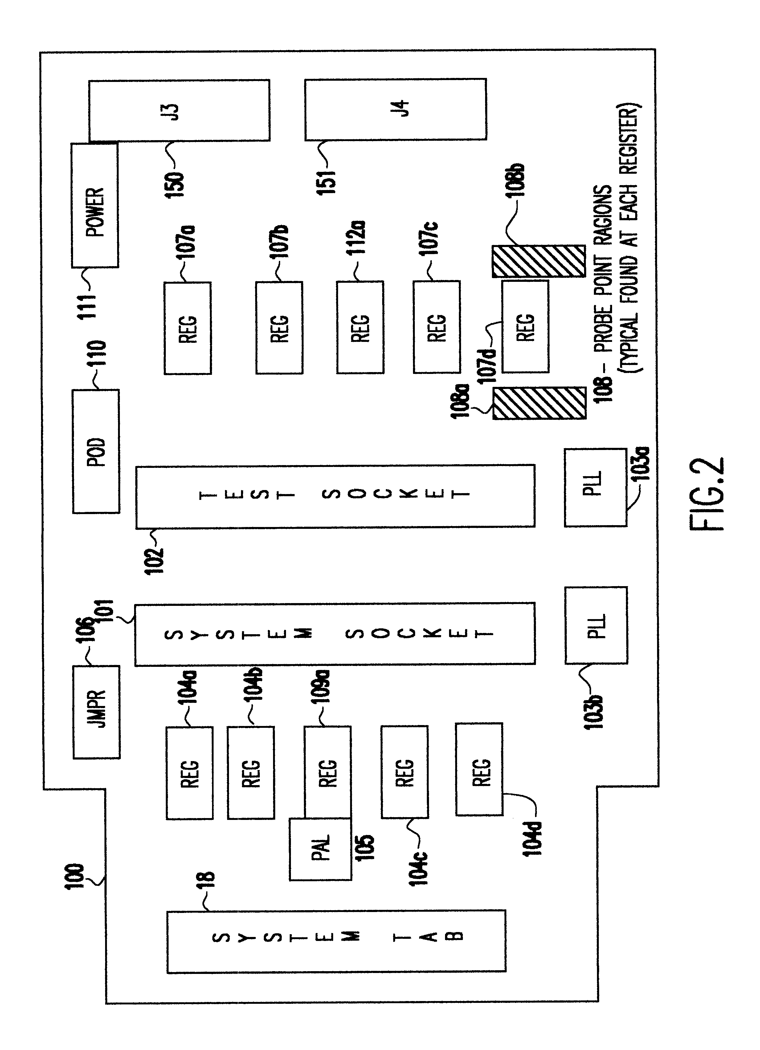
It is another object of the invention to provide a test assembly that re-drives the system clocks with a phase lock loop (PLL) buffer to a DIMM socket on the test assembly to permit timing adjustments to minimize the degradation to the system's memory bus timings due to the additional wire length.
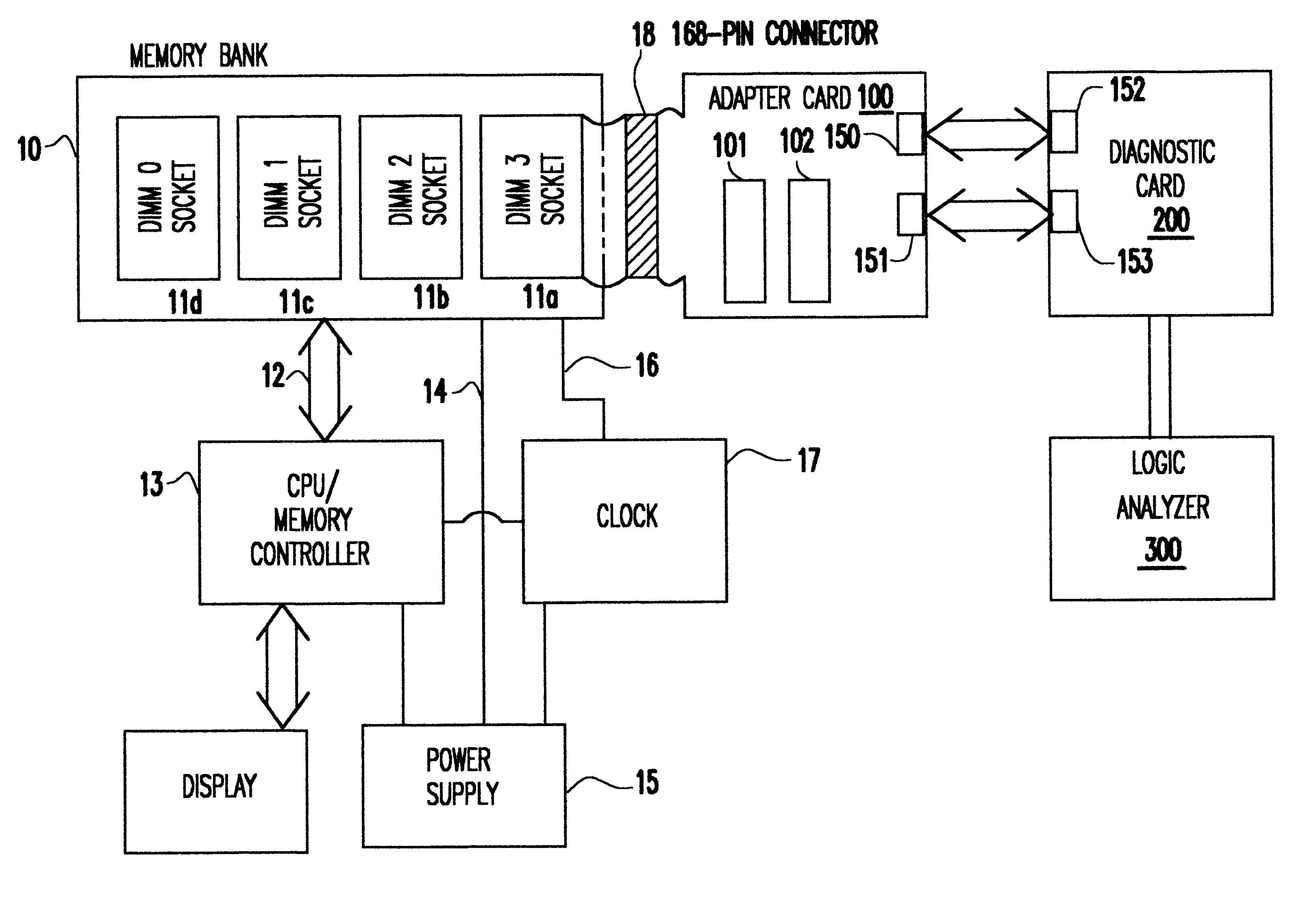
The test assembly provides failure information in real time via the logic analyzer display. A logic analyzer is connected to the diagnostic card via cables. The product engineer can monitor device fails under actual operating conditions via the logic analyzer. Any use of the invention will require that the user has a memory module that is suspected of causing a failure in a PC application. First the adapter card must be installed in a memory socket of the PC. The suspect memory module may be installed in either the system socket of the adapter card or the test socket. If the system socket is used, the memory faults will cause aberrant behavior in the PC application, perhaps a line of diagnostic output in a test program or a system crash in a non-robust application. This will allow for rough visual correlation between that failure event and an error detected by the present invention in that the light emitting diodes (LEDs) will light or the Logic Analyzer will trigger at the same time the PC shows the fault. If the suspect module is installed in the test socket, the PC application will not show the fault, but will indicate that a memory failure has occurred. One skilled in the art of diagnosing memory fails will understand to connect their logic analyzer in a fashion meaningful to the problem at hand and to receive the type of information required.

Problems solved by technology

This might takes months for the product engineer to capture actual cycle or multiple cycles that cause the fail.
A significant risk to this method is that the software may not capture the fail.
Processors have become too complex for the software to control the hardware by stepping cycles.
A memory module tester can not duplicate the exact conditions in which these Synchronous DIMMs fail.
Present adapter cards cause system failures in systems with memory bus timings at 100 MHz and above, mostly due to the additional wire lengths introduced with the adapter card.
If the system socket is used, the memory faults will cause aberrant behavior in the PC application, perhaps a line of diagnostic output in a test program or a system crash in a non-robust application.
If the suspect module is installed in the test socket, the PC application will not show the fault, but will indicate that a memory failure has occurred.

Method used


Image

  • Captured synchronous DRAM fails in a working environment
  • Captured synchronous DRAM fails in a working environment
  • Captured synchronous DRAM fails in a working environment

Examples


Embodiment Construction

The present invention permits good and questionable synchronous memory modules to be compared using an external logic analyzer. It permits resolution of in-system fails that occur uniquely in system environments. Existing adapter / diagnostic cards do not have a facility to modify the system clock to adjust for hold and setup time violations that occur when the adapter / diagnostic card is introduced in a system. Present adapter cards do not fully support characterizing Unbuffered DIMMS or Registered DIMMs. The present invention provides Product engineers with an adapter / diagnostic card that permits probing the system memory bus without degrading system bus timings, as well as characterizing either Register DIMMs or Unbuffered Synchronous DIMMs.

The present invention operates in an actual operational environment testing synchronous DRAM-based memory cards. It operates at the memory interface monitoring the bus cycles which allow the user to:

isolate the problem on the memory,

analyze the p...


PUM


Abstract

A Synchronous DRAM memory test assembly that converts a normal PC or Workstation with a synchronous bus into a memory tester. The test assembly may be split into two segments: a diagnostic card and an adapter card to limit mechanical load on the system socket as well as permit varying form factors. This test assembly architecture supports memory bus speeds of 66 MHz and above, and provides easy access for a logic analyzer. The test assembly supports Registered and Unbuffered Synchronous DRAM products. The test assembly permits good and questionable synchronous modules to be compared using an external logic analyzer. It permits resolution of in-system fails that occur uniquely in system environments and may be otherwise difficult or impossible to replicate. The test assembly re-drives the system clocks with a phase lock loop (PLL) buffer to a memory module socket on the test assembly to permit timing adjustments to minimize the degradation to the system's memory bus timings due to the additional wire length and loading. The test assembly is programmable to adjust to varying bus timings such as: CAS (column address strobe) Latencies and Burst Length variations. It is designed with Field Programmable Gate Arrays (FPGAs) to allow for changes internally without modifying the test assembly.

Description

1. Field of the InventionThe present invention generally relates to capturing and identifying failures in memory cards and, more particularly, to testing Dual In-line Memory Modules (DIMMs) to determine the cause and location of failures in a system environment.2. Background DescriptionThe industry for Personal Computers (PCs), Workstations and Laptops is building high performance systems that are utilizing Synchronous Dynamic Random Access Memories (SDRAMs). As central processing units (CPUs) become faster, memory buses must be implemented to operate at higher speeds so as not to bottleneck the system. Memory card designers are designing pluggable synchronous memory assemblies, such as Dual In-Line Memory Modules (DIMMs), to operate at synchronous memory bus speeds of 66 MHz and above.Product engineers are required to identify root cause synchronous memory fails in real time systems. Software can be used to exercise the memory and capture the fail. This might takes months for the p...

Claims


Application Information

Patent Timeline
Patent Type & Authority Patents(United States)
IPC IPC(8): G06F11/277G06F11/273G11C29/56
CPCG11C29/56G11C29/56012G11C2029/5602
Inventor CONNOLLY, BRIAN J.GRUNDON, STEVEN A.HAZELZET, BRUCE G.KELLOGG, MARK W.MALLABAR, JAMES R.
Owner GLOBALFOUNDRIES INC
Learn More