
Fuel hose

a technology of fuel hoses and hoses, which is applied in the direction of transportation and packaging, mechanical equipment, propulsion parts, etc., can solve the problems of poor flexibility and sealing properties of fluororesin, gasoline may be forced to remain in the gasoline tank for a long time to deteriorate gasoline, and the fuel hoses prepared only from nbr/pvc cannot cope fully with such fuel permeation regulation

Inactive Publication Date: 2002-10-22
SUMITOMO RIKO CO LTD
View PDF13 Cites 24 Cited by
  • Summary
  • Abstract
  • Description
  • Claims
  • Application Information

AI Technical Summary

Benefits of technology

The fuel hose of the first aspect has excellent resistance to fuel and resistance to permeation because of the fluororesin layer formed and particularly shows high reliability for the alcohol-containing gasoline and sour gasoline. Particularly when the innermost layer of the fuel hose is the fluororesin layer, the fuel hose exhibits the resistance to fuel most efficiently.
Since the rubber forming the rubber layer of the fuel hose contains from 2 to 15 phr of the phenol-type resin, adhesion to the fluororesin layer can be ensured without relying upon the vulcanization adhesion. Accordingly, first, the fuel hose can avoid troubles such as blocking of the flow path and reduction in vibration durability of the fuel hose caused by weak adhesion of the rubber layer to the fluororesin layer. Secondly, the formation of the thin fluororesin layer can be satisfactorily performed through the electrostatic powder coating, because it requires no extrusion which is needed in vulcanization adhesion
Furthermore, resin in general tends to deteriorate in resin performance when adhesive agents are added thereto. In the first aspect, the phenol-type resin is added to the rubber forming the rubber layer, and no adhesion agent is added to the fluororesin forming the fluororesin layer, thus to avoid the deterioration in performance of the fluororesin layer.
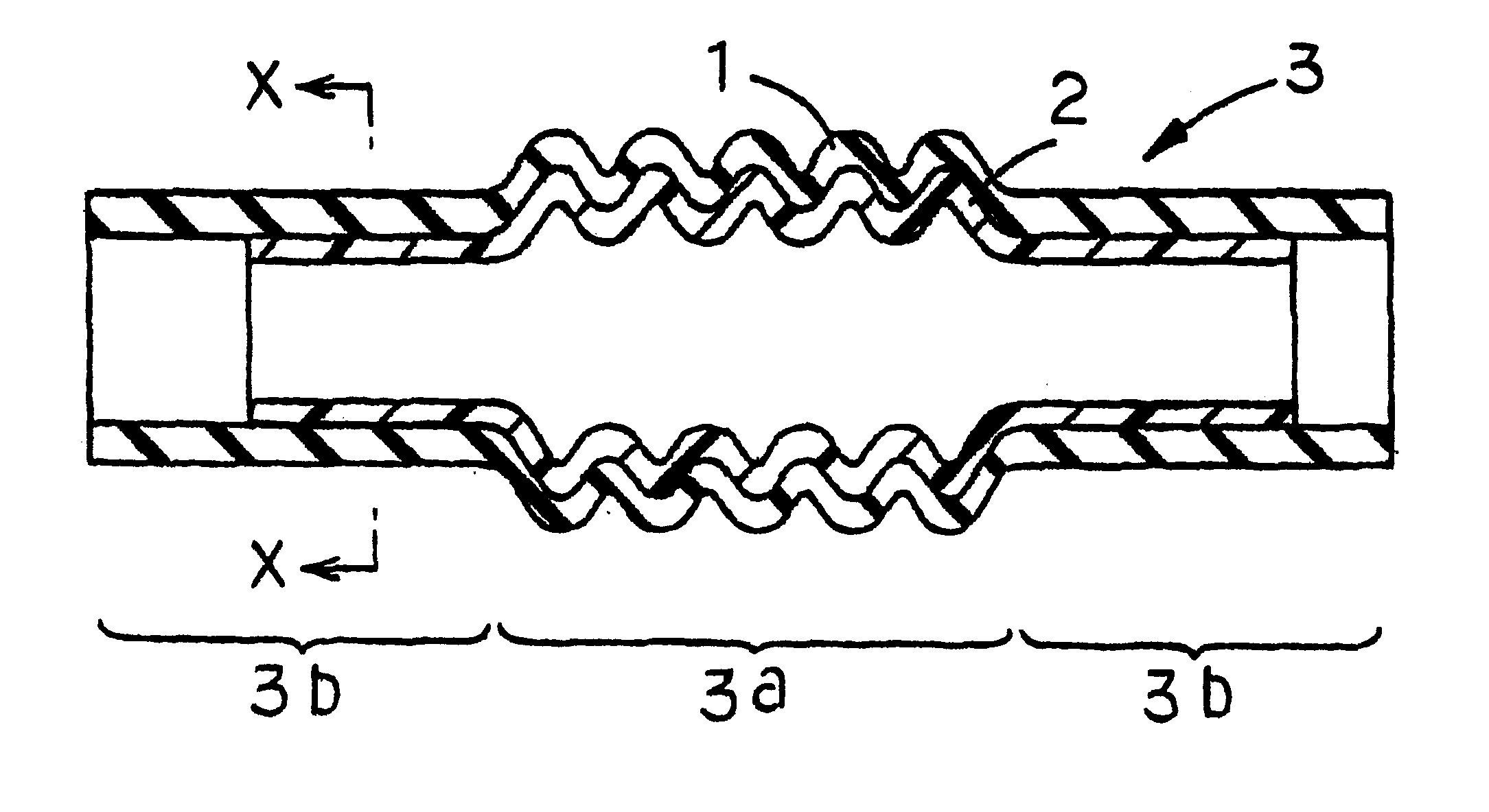
In the second aspect, a good thin fluororesin layer is formed by the powder coating. Furthermore, the thin fluororesin layer can be formed with ease in an arbitrary form and at an arbitrary portion of the hose. The arbitrary form is, for example, a smooth tubular form, a corrugated form, or a tubular form having a concave portion for containing a seal ring or other concave and / or convex portions. The arbitrary portion of the hose is, for example, the entire inner surface of a tubular rubber layer or the inner surface excluding end portions of the inner surface of the tubular rubber layer.
Since the fluororesin layer can be shaped, for example, into a corrugated form as described above, the flexibility of the fuel hose is ensured with ease. Furthermore, since the fluororesin layer can be formed on the inner surface of the rubber layer excluding the end portions thereof, the sealing at the hose joints can be ensured with ease. Moreover, for example, when the concave portion for containing a seal rubber ring is formed on the end inner surface of the rubber layer, the fluororesin layer can also be formed on the concave portion with ease. Accordingly, the sealing can be ensured with ease while maintaining the low permeability to fuel.
In a third aspect of the invention, the thickness of the fluororesin layer according to the first or second aspect is from 0.05 to 0.5 mm. In the third aspect, the thickness of 0.05 mm or more makes it possible to ensure particularly effectively the resistance to fuel of the fuel hose and resistance to permeation of the fuel. The thickness of 0.5 mm or less makes it possible to ensure particularly fully the flexibility of the fuel hose.

Problems solved by technology

Conventional fuel hoses prepared only from NBR / PVC have been unable to cope fully with such fuel permeation regulation.
Furthermore, when an automobile is left to stand for a long period of time, the gasoline may be compelled to remain in the gasoline tank for a long time to deteriorate the gasoline.
However, since fluororesin has poor flexibility and sealing properties at hose joints, a fuel hose formed of a fluororesin layer alone is not suitable.
Fluoropolymers in general have a disadvantage of having weak adhesion to rubber materials, and fluororesins in particular are serious in this defect.
In preparation of the fuel hose having a rubber layer formed on the outer surface of a thinned fluororesin layer, the adhesion of both layers presents a serious problem.
That is, they do not disclose a technique allowing adhesion of the fluororesin layer to a rubber layer vulcanized already.
When the fluororesin layer and the unvulcanized rubber layer are allowed to adhere by vulcanization, electrostatic powder coating of the fluororesin layer onto the unvulcanized rubber layer is difficult.
Therefore, the formation of a good thin fluororesin layer by the electrostatic powder coating is also difficult.
The conventional technique of the aforesaid Japanese Patent Application Laid-Open No. 255004 / 1994 relates to a technical problem in adhesion of the thinned fluororesin layer to the vulcanized rubber layer.
These pretreatments for adhesion complicate the production process to deteriorate production efficiency and production cost.
Furthermore, resin in general tends to deteriorate in resin performance when adhesive agents are added thereto.
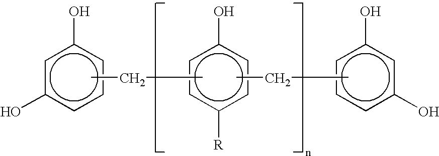
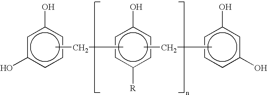
When the content of the phenol-type resin in the rubber forming the rubber layer is less than 2 phr, adhesion to the fluororesin may be deteriorated, and the resistance of the rubber layer itself to the sour gasoline also tends to become insufficient, particularly when epichlorohydrin rubber is used.
The VDF molar ratio exceeding the above range results in raising excessively the melting temperature of the fluororesin and results in an increase of the rigidity of the fluororesin layer.
Contrarily, the VDF molar ratio not reaching the above range causes excessive reduction in the melting temperature of the fluororesin relative to the temperature of the fuel hose in use, and invites deterioration in resistance to gasoline permeation.
The phenol-type resin content less than 2 phr may result in reduced adhesion to the fluororesin layer and insufficient resistance to sour gasoline of the rubber layer itself, particularly concerning epichlorohydrin rubber.

Method used


Image

  • Fuel hose
  • Fuel hose
  • Fuel hose

Examples


Embodiment Construction

, Examples 32 to 40, and Comparative Examples 1 and 4, NBR-PVC, epichlorohydrin rubber, CPE, and CSM having compositions as shown in the corresponding columns of Tables 8 to 13 were prepared. These rubber compositions were subjected to vulcanization molding by use of an injection molding machine at 160.degree. C. for five min. to prepare rubber tubes having a single-layer structure of a corrugated form, which had an inner diameter of 35 mm, a wall thickness of 4 mm, and a length of 200 mm.

Subsequently, the inner surfaces of the rubber tubes according to the aforesaid examples and comparative examples (excluding Examples 38 to 40 and Comparative Example 4) underwent the electrostatic powder coating of a fluororesin copolymer powder to form layers of 0.2 mm thickness although these were not described in the tables. The fluororesin copolymer was a VDF-CTFE copolymer having a VDF / CTFE molar ratio of 95 / 5. The electrostatic coating was carried out through corona discharge (minus charge) ...


PUM


Abstract

A fuel hose comprising a rubber layer and a fluororesin layer formed on the inner surface of the rubber layer, in which the adhesion to the fluororesin layer is improved by blending from 2 to 15 phr of a phenol-type resin with the rubber forming the rubber layer. Phenol resins of a specific polymeric structure are particularly preferred as the phenol-type resins. A fluororesin layer formed by melting a fluororesin and allowing it to adhere to the inner surface of the rubber layer by powder coating is particularly preferred. The provision of the fluororesin layer on the inner surface of the rubber layer enables simple and effective adhesion of the thinned fluororesin layer to the rubber layer.

Description

1. Field of the InventionThe present invention relates to a fuel hose having at least a rubber layer and a fluororesin layer formed on the inner surface thereof. The fuel hose of the invention is favorably used, for example, as a fuel hose for automobiles and exhibits excellent performance particularly for alcohol-containing gasoline and sour gasoline.2. Description of the Related ArtIn recent years, control led evaporation of fuel to the air has been demanded in relation to environmental pollution. Therefore, the fuel permeability of the fuel hose for automobiles has been more and more strictly regulated. Conventional fuel hoses prepared only from NBR / PVC have been unable to cope fully with such fuel permeation regulation. Further, the alcohol-containing gasoline used to purify automobile exhaust shows high permeation as compared with gasoline containing no alcohol. A fuel hose having further lower permeability to fuel has therefore been expected. Furthermore, when an automobile is...

Claims


Application Information

Patent Timeline
IPC IPC(8): F16L11/04B32B1/08B60K15/01F16L11/11
CPCF16L11/04F16L2011/047Y10S138/07
Inventor IIO, SHINJIITO, HIROAKI
Owner SUMITOMO RIKO CO LTD
Learn More