
Method and apparatus for recovering energy from wastes by combustion in industrial furnaces

Inactive Publication Date: 2002-10-29
CEMEX DE C V
View PDF19 Cites 28 Cited by
  • Summary
  • Abstract
  • Description
  • Claims
  • Application Information

AI Technical Summary

Benefits of technology

One of the main goals of this invention is to provide an improved method and apparatus for an efficient recovery of the energy contained in wastes by means of combustion of the same in industrial furnaces.
Still another objective of the invention, is to provide an improved method and apparatus for elimination of hazardous waste in a rotary furnace or similar equipment, in order to burn and disintegrate such waste until non-toxic effluents are obtained, which will produce no atmospheric pollution and no environmental damage.

Problems solved by technology

On the other hand, it has been found, that all industrial processes in general produce waste that can be burned.
The EPO publication instead teaches a significantly more complex apparatus requiring not only significant added capital cost, but also more complicated control variables.
The aforementioned European patent application characterizes the Oct. 20, 1981, U.S. Pat. No. 4,295,823 as utilizing the exhaust gases from the rotary kiln for the decomposition of waste and notes that such a method makes it difficult for the kiln gases to move up through the decomposition chamber in a controlled flow due to the high temperature and further that such utilization of the kiln gases for decomposition of the waste materials will have a disturbing effect on the draft conditions of the kiln system.
Also none of the disclosed embodiments teach any decomposition of the waste material by means of the tertiary air alone.
All of these six variations have the common disadvantage emphasized at the top of page two of the aforementioned European patent.
Consequently, the contribution of the waste to reduce fuel consumption is very poor.
This type of alternate fuel, when sufficient oxygen is found in the furnace gases, causes the formation, in furnaces with a calciner, of a hot spot that permits partial formation of a liquid phase with sufficient increase in adhesion between the particles to result in agglomeration, forming an internally adherent crust or rings, causing energy inefficiency (such as higher consumption of electrical power due to a higher drop in pressure, etc.).
Additionally, there are operative problems from dust retention behind such rings.
The furnace is also fed by means of a rotary scoop, and thus the operational cost is increased due to the need to purchase the above mentioned agent.
However, it has disadvantages due to the fact that since the hatch is rotating, only one drum can only be fed for every full turn of the rotary furnace.
This is a serious limitation.
In addition, the patent retains many of the disadvantages already described for the other above-mentioned inventions directed to feeding a rotary furnace.
This also has disadvantages, since the furnace's operation itself is degraded and all operational conditions are substantially altered.
Additionally, the resulting product's composition is also affected.
and this reaction triggers volatile cycles (SO.sub.2), that result in operational disturbances.
Also, the operational complexity of this system makes it prone to plugging of the mentioned cannon, with the solid materials that it is pushing.
As can be seen in the above, the operation of this system is complex and the fact that an additional burner is considered, rises considerably the equipment and operational costs, thus it is not a satisfactory solution, apart from having the same disadvantages already mentioned for inventions that feed into the rotary furnace when there is a calciner.
However, due to the way in which such modules are fed, there is no ground-breaking contribution, since the already known feeding pipes are being used and, thus, the already known disadvantages also remain, especially for furnaces with a calciner.
Feeding combustible material to the upper stages (first to third) of a pre-heater, makes it prone to discharging hydrocarbons due to lack of residence time and due to the temperature for combustion of solid materials.
That type of feed still shows disadvantages, for which reason a satisfactory and effective solution has not been achieved.

Method used


Image

  • Method and apparatus for recovering energy from wastes by combustion in industrial furnaces
  • Method and apparatus for recovering energy from wastes by combustion in industrial furnaces
  • Method and apparatus for recovering energy from wastes by combustion in industrial furnaces

Examples


Embodiment Construction

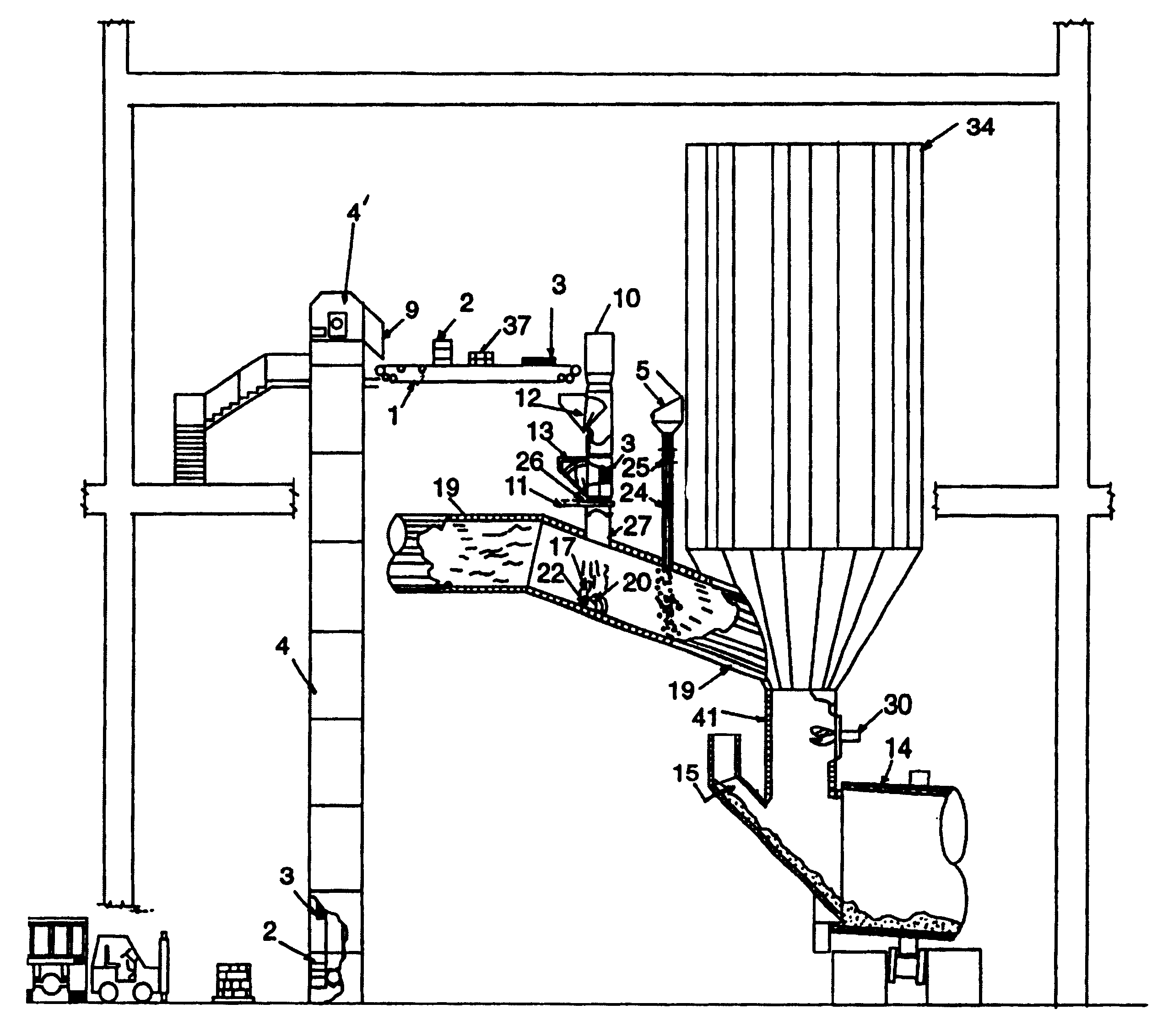
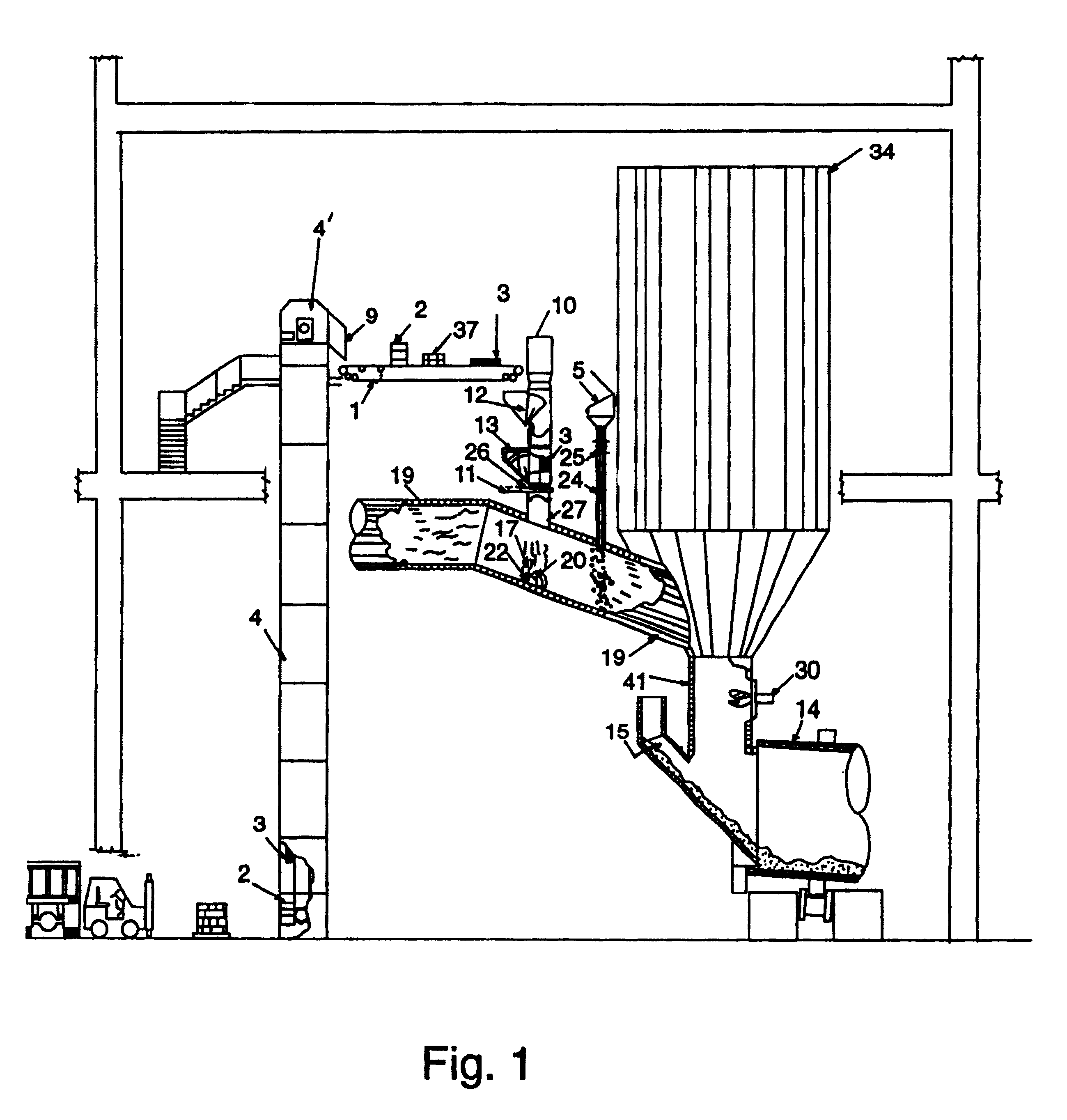
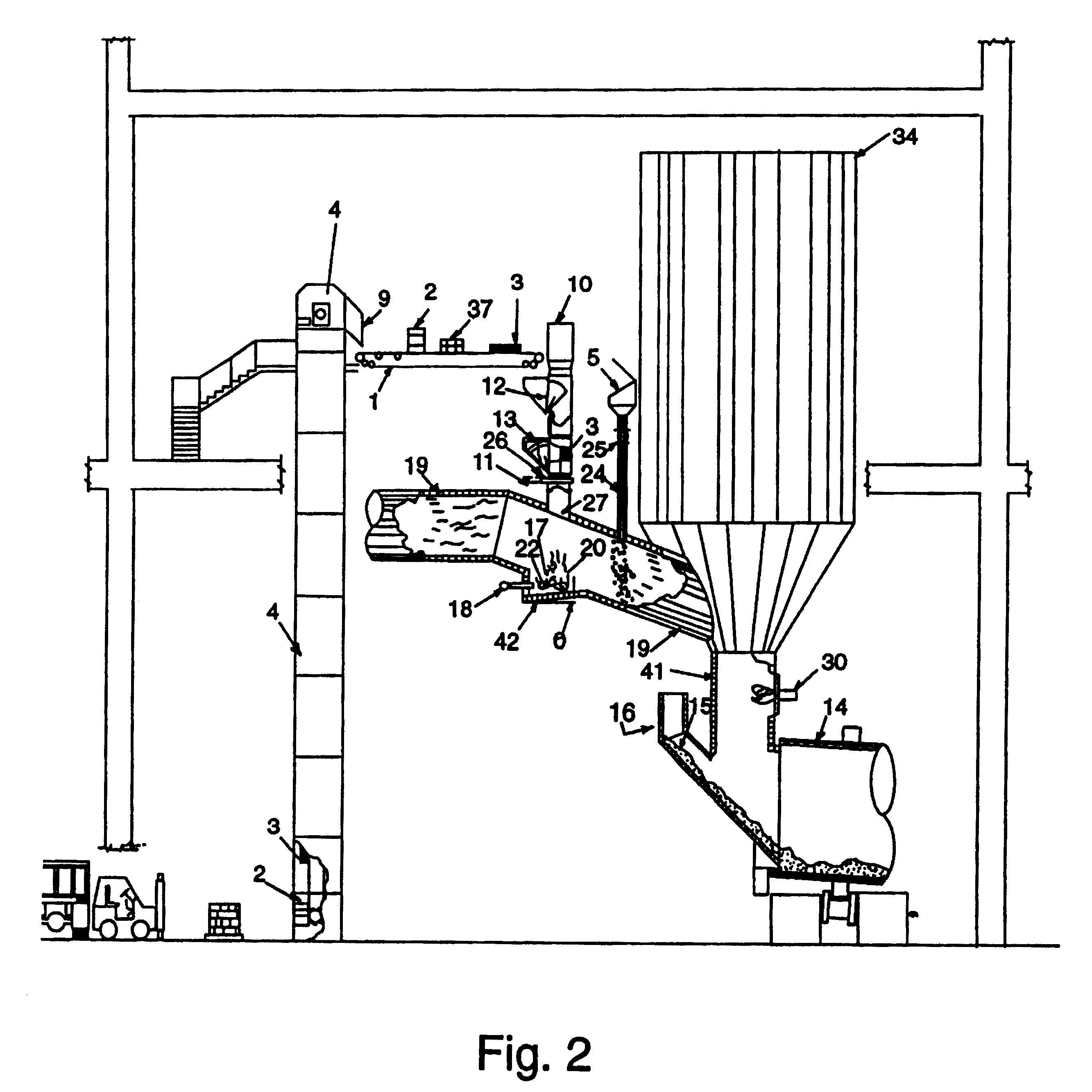
A detailed description of this invention will be provided hereafter, and reference will be made to drawings above, in which arabic numbers have been included to identify the elements of parts of the novel apparatus, and such numbers of those parts coincide with the description following.

As shown in FIG. 1, in accordance with the novel method and apparatus of this invention, the bulk or crushed solid material that is to be used for recovery of its energy by means of combustion, is batch fed to the tertiary air duct 19. The solid material (such as a container 2 or tire 3) is placed inside an elevator 4 and elevated thereby to point 4' thereof to an unloading station 9. There it is loaded onto a belt conveyor 1, that feeds the material (shown as container 2, tires 3, or even bales of solid material 37) to a first vertical feed hopper 10. At the bottom of the hopper 10 are some gates 12 and 13, used to control the feed of the solid waste material, and which serve also to isolate the atm...


PUM

PropertyMeasurementUnit
Fractionaaaaaaaaaa
Angleaaaaaaaaaa
Distanceaaaaaaaaaa

Abstract

Method and apparatus to recover energy from waste by means of combustion of such waste in industrial furnaces, particularly of the rotary type, that has an external calciner, feeding such waste into the tertiary air duct of the calciner and burning the waste inside the duct itself, to efficiently make use of the energy produced by such combustion, as a contribution of the total cost of fuel necessary to operate the industrial furnace. The method and apparatus permit the elimination of hazardous wastes that are efficiently disassociated when burned sufficiently to produce effluents that are typically non-toxic, producing greatly reduced or even no atmospheric pollution nor environmental damage.

Description

BACKGROUND OF INVENTIONThis invention discloses and claims an improved method and equipment to recover energy from wastes by combustion of same in industrial furnaces.This invention allows an efficient use of the heating power of volatile components in waste materials, preferably solids whether in bulk or crushed, such as vehicle tires, bags, bales, bulk material that may be contained in tanks, barrels, etc. to dramatically reduce fuel consumption expenses in large capacity industrial furnaces, particularly of the rotary kiln type, used in the cement or similar industries.In the past, the need to diminish as much as possible the amount of solid, gas or liquid primary fuel that needs to be burned in large capacity industrial furnaces, in order to achieve a more efficient and productive operation of the same at a lower cost, has been recognized.On the other hand, it has been found, that all industrial processes in general produce waste that can be burned. Many such wastes, because of ...

Claims


Application Information

Patent Timeline
IPC IPC(8): C04B7/00C04B7/44F27B7/42F27B7/34F27B7/20F27D23/00F27D99/00
CPCC04B7/4423F27B7/34F27B7/42F23G2206/201F27D2099/0051Y02E50/30Y02E20/30Y02P40/125
Inventor ARROYAVE-GARCIA, JOSE LUISBERRUN-CASTANON, JORGEDIOSDADO, JUAN MANUELFARIAS, LUISGARCIA, ARMANDO J.GARZA-ONDARZA, JAVIERGONZALEZ-GUERRA, SIMONMAYORAL-RODRIGUEZ, IGNACIO M.MORALES-PEREGRINA, JUAN JOSEPADILLA-CORTEZ, ALEJANDRO
Owner CEMEX DE C V
Learn More