Process for applying electrode layers to a polymer electrolyte membrane strip for fuel cells

Inactive Publication Date: 2002-12-31
DMC2 DEGUSSA METALS +1
View PDF9 Cites 108 Cited by
  • Summary
  • Abstract
  • Description
  • Claims
  • Application Information

AI Technical Summary

Benefits of technology

can be achieved by a process for applying electrode layers on to a polymer electrolyte membrane strip in a desired pattern, wherein the front and back of the membrane are continuously printed with the electrode layers in the desired pattern using an ink containing an elect

Problems solved by technology

Many different processes exist for the production of membrane-electrode assemblies, but only a few of them are suitable for industrial purposes, i.e. for continuous manufacture on a large scale at economic costs.
In addition, this process is associated with a high risk of pinhole formation

Method used


Image

  • Process for applying electrode layers to a polymer electrolyte membrane strip for fuel cells
  • Process for applying electrode layers to a polymer electrolyte membrane strip for fuel cells
  • Process for applying electrode layers to a polymer electrolyte membrane strip for fuel cells

Examples


example 1

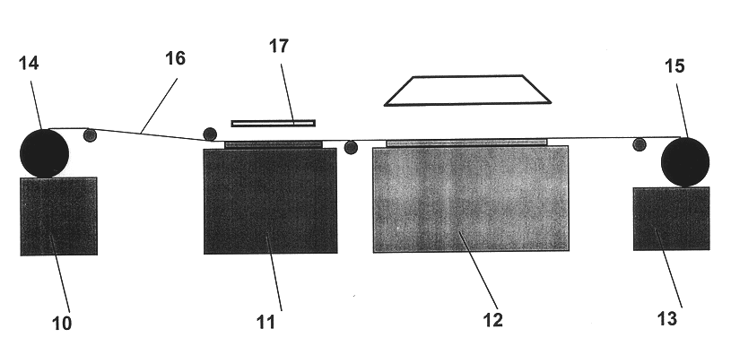
A 10 meter long and 0.3 meter wide piece of polymer electrolyte film of the NAFION.RTM. NE 1035 type was provided in the form of a roll. The water content of the membrane was 2 wt. %. The membrane was in the Na.sup.+ form. The membrane was printed with the electrode layers on a strip coating line as shown in FIG. 4. The polymer electrolyte film was fed to the screen printing station by means of the unwinding and transport device. In the screen printing station the film was printed with consecutive electrode layers measuring 14.9 cm.times.24.7 cm using the ink specified above.

The average speed of the membrane through the coating line was 300 m / h. The individual electrode segments were printed on the membrane at a distance of 6 cm from one another.

To dry the freshly printed electrode layers, after leaving the screen printing station, the membrane was passed continuously through a circulating air drier where the solvent components of the printing ink were removed at 90.degree. C. and t...

example 2

Using a membrane of the same type as in Example 1, another coating test was carried out. In contrast to Example 1, the water content of the membrane was adjusted to 20 wt.% prior to each coating. For this purpose, a soaking bath was inserted in the coating line of FIG. 4 upstream of the screen printing station (see FIG. 5). The temperature of the soaking bath was 60.degree. C.

Apart from this difference, the coating was carried out exactly as in Example 1.

example 3

This example was carried out exactly as in Example 2. In contrast to Example 2 a polymer membrane of the NAFION.RTM. NE 112 type was used. This is a polymer membrane in the acid H.sup.+ form. To coat this membrane an ink was prepared having the composition described above, but omitting the tetrabutylammonium hydroxide. The electrode layers were dried at 70.degree. C.

Testing of the Membrane-electrode Assemblies

One segment was cut out of each of the three coated membranes and reprotonated by treating for one hour in 0.5 M sulfuric acid. A piece of the coated area measuring 9 cm.times.9 cm was then cut out of each, combined with gas diffusion structures and installed in a polymer electrolyte membrane test cell with an active area of 50 cm.sup.2. The cell was tested in hydrogen / air operation under a gas pressure of 3 bar. The cell temperature was 75.degree. C. The gas streams were humidified at 85.degree. C. (anode) and 60.degree. C. (cathode). The gas stoichiometry was 1.5 for hydrogen...


PUM

PropertyMeasurementUnit
Angleaaaaaaaaaa
Fractionaaaaaaaaaa
Electric potential / voltageaaaaaaaaaa

Abstract

A process is disclosed for applying electrode layers to a polymer electrolyte membrane strip in a desired pattern, wherein the front and back of the membrane are continuously printed with the electrode layers in the desired pattern using an ink containing an electrocatalyst, and the printed electrode layers are dried at elevated temperature immediately after the printing operation, the printing taking place while maintaining accurate positioning of the patterns of the electrode layers on the front and back in relation to one another.

Description

INTRODUCTION AND BACKGROUNDThe present invention relates to a process for applying electrode layers to a polymer electrolyte membrane strip in a desired pattern.Fuel cells convert a fuel and an oxidizing agent, physically separated from one another, into electricity, heat and water at two electrodes. Hydrogen or a hydrogen-rich gas can be used as the fuel and oxygen or air as the oxidizing agent. The energy conversion process in the fuel cell is distinguished by particularly high efficiency. For this reason, fuel cells in combination with electric motors are gaining increasing importance as an alternative to conventional combustion engines for automotive vehicles.The so-called polymer electrolyte membrane fuel cell (PEMFC) is suitable for use as an energy converter in motor vehicles thanks to its compact construction, its power density and its high efficiency.The central component in a PEMFC is the so-called membrane-electrode assembly (MEA). This consists of a polymer electrolyte m...

Claims


Application Information

Patent Timeline
IPC IPC(8): C25B9/06C25B9/10H01M8/10B05D7/04H01M4/88C25B9/23H01M8/1004
CPCB41M1/26B41M1/30B41M3/008C25B9/10H01M8/1004B41M3/006B41M1/04B41M1/06B41M1/10B41M1/12Y10T29/49115H01M2300/0082Y02E60/521Y02P70/50Y02E60/50C25B9/23B05D7/04
Inventor STARZ, KARL-ANTONZUBER, RALFGOTTENAUER, WOLFGANGFEHL, KNUTDIEHL, MANFRED
Owner DMC2 DEGUSSA METALS
Why Eureka
Try Eureka