Optical transparent film and sputtering target for forming optical transparent film

a technology of optical transparent film and sputtering target, which is applied in the manufacture of optical record carriers, conductive layers on insulating supports, record information storage, etc., can solve the problems of insufficient study of the feasibility of improving the manufacturing process steps of zns--sio.sub.2 targets, and the productivity of low-level workers is significantly reduced. , to achieve the effect of reducing the formation of particles

Inactive Publication Date: 2003-03-04
JX NIPPON MINING& METALS CORP
View PDF12 Cites 69 Cited by
  • Summary
  • Abstract
  • Description
  • Claims
  • Application Information

AI Technical Summary

Benefits of technology

The above ZnO-based sputtering target for optical disk protective films of the present invention can significantly reduce the formation of particles compared with conventional ZnS--SiO.sub.2 targets. The reason is considered that ZnO and the additives themselves have larger adhesive force to the internal walls of the chamber and to the apparatus than ZnS.
By thus reducing the formation of particles, since the number of interruption or discontinuance of sputtering decreases, and the frequency of troublesome cleaning of the sputtering chamber decreases, the present invention has the effect of dramatically elevating the...

Problems solved by technology

This lowers productivity significantly.
However, the solution more than the estimation has not been found.
Also, although the protective films formed by sputtering have been required to have a reflectance as low as possible, the feasibility of the improvement in the steps of the manufacturing process of the ZnS--SiO.sub.2 target has not been sufficiently studied.
Especially, the large problem of the above-...

Method used


Image

  • Optical transparent film and sputtering target for forming optical transparent film
  • Optical transparent film and sputtering target for forming optical transparent film
  • Optical transparent film and sputtering target for forming optical transparent film

Examples


example 1

An example related to an optical disk protective film will be shown. A target was manufactured by weighing 2% by weight of Al.sub.2 O.sub.3 powder and 10% by weight of Nb.sub.2 O.sub.5 powder, mixing them with balance ZnO powder, and sintering the mixture in the air at 1400.degree. C. The resultant target had a density of 5.3 g / cm.sup.3.

Using the ZnO--Al.sub.2 O.sub.3 --Nb.sub.2 O.sub.5 target thus obtained, sputtering was performed to form a film on a substrate. The sputtering conditions were as follows:

The number of substrate coating, i.e. the number of products, until particles on the internal walls of the sputtering chamber and the apparatus had to be cleaned was 3000 to 3500. This was 20%-40% improvement compared with the number of products from the Comparative Examples described below (ZnS--SiO.sub.2 target).

The reflectance of the protective films was 16-18%, which sufficiently achieved the target value of 20% or less. Furthermore, the transmittance in the visible-ray region w...

example 2

A target was manufactured by weighing 2% by weight of Al.sub.2 O.sub.3 powder and 5% by weight of SiO.sub.2 powder, mixing them with balance ZnO powder, and sintering the mixture in the air at 1400.degree. C. The resultant target had a density of 5.2 g / cm.sup.3.

Using the ZnO--Al.sub.2 O.sub.3 --SiO.sub.2 target thus obtained, sputtering was performed to form a film on a substrate. The number of substrate coating, i.e. the number of products, until particles on the internal walls of the sputtering chamber and the apparatus had to be cleaned was 3000 to 3500. This was 20%-40% improvement compared with the number of products from the Comparative Examples described below (ZnS--SiO.sub.2 target).

The reflectance of the protective films was 16-18%, which sufficiently achieved the target value of 20% or less. Furthermore, the transmittance in the visible-ray region was 93% or more, and the properties of an effective protective film were obtained.

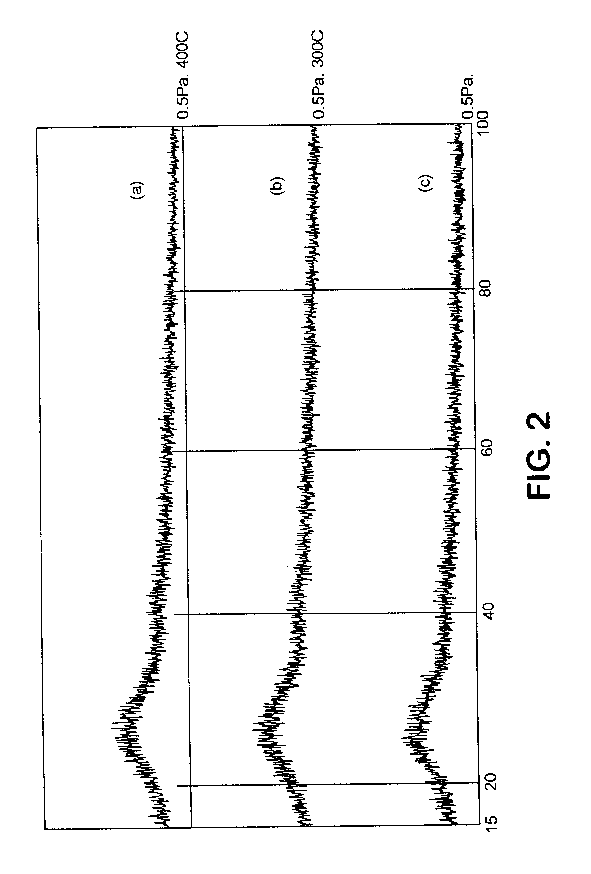
Also, X-ray diffraction data were reviewed to...

example 3

A target was manufactured by weighing 2% by weight of Ga.sub.2 O.sub.3 powder and 10% by weight of Nb.sub.2 O.sub.5 powder, mixing them with balance ZnO powder, and sintering the mixture in the air at 1400.degree. C. The resultant target had a density of 5.2 g / cm.sup.3.

Using the ZnO--Ga.sub.2 O.sub.3 --Nb.sub.2 O.sub.5 target thus obtained, a film was formed on a substrate by direct current (DC). The number of substrate coating, i.e. the number of products, until particles on the internal walls of the sputtering chamber and the apparatus had to be cleaned was 3000 to 3500. This was 20%-40% improvement compared with the number of products from the Comparative Examples described below (ZnS--SiO.sub.2 target).

The reflectance of the protective films was 16-18%, which sufficiently achieved the target value of 20% or less. Furthermore, the transmittance in the visible-ray region was 93% or more, and the properties of an effective protective film were obtained.

Also, X-ray diffraction data ...


PUM

PropertyMeasurementUnit
Percent by massaaaaaaaaaa
Pressureaaaaaaaaaa

Abstract

To provide an optically transparent film containing 0.01 to 20% by weight glass forming oxide consisting of Nb2O5, V2O5, B2O3, SiO2, and P2O6; 0.01 to 20% by weight Al2O3 or Ga2O3; and 0.01 to 5% by weight hard oxide of ZrO2 and TiO2 as required; balance being ZnO, and a sputtering target for forming such a film. This sputtering target reduces occurrence of particles during sputtering, decreases the number of interruption or discontinuance of sputtering to improve production efficiency, and forms a protective film for optical disks with large transmittance and low reflectance.

Description

The present invention relates to an optically transparent film especially used in a protective film (hereafter including a material expressed as a "layer") for optical disks, more specifically to an optically transparent film that can decrease the number of particles formed during the formation of a film with sputtering, that has a high transmittance in the visible region of the formed film, and that is suitable for an optical disk having a low reflectance, in particular for a phase-change type optical disk; and a sputtering target for forming such a film.In recent years, high-density optical disks have rapidly attracted public interests because they can record and play without the need of magnetic heads.These optical disks are classified into three types: the read-only type, the write-once type, and the rewritable type, and the phase-change system used in the write-once type and the rewritable type has particularly attracted public attention. The principle of writing and reading us...

Claims


Application Information

Patent Timeline
IPC IPC(8): C23C14/34C23C14/08G11B7/243G11B7/24G11B7/254G11B7/257G11B7/26C23C14/10C03C17/245C04B35/00C04B35/457G11B7/2578H01B1/08H01B5/14
CPCC23C14/08C23C14/10C23C14/3414G11B7/243G11B7/257G11B7/26G11B2007/25715G11B2007/25706G11B2007/25708G11B2007/2571G11B7/2578C03C17/245C03C2217/23C03C2218/154C03C2218/32
Inventor KUWANO, KATSUOTAKAMI, HIDEO
Owner JX NIPPON MINING& METALS CORP
Why Eureka
Try Eureka