Electrophotographic photosensitive member, process cartridge and electrophotographic apparatus

a photosensitive member and electrophotography technology, applied in the direction of electrographic process apparatus, corona discharge, instruments, etc., can solve the problems of chemical, electrical and mechanical impacts on the surface layer of the photosensitive member, and the use of a principally photoconductive polymer such as poly, vinylcarbazole and a charge transfer complex formed of 2,4,7-trinitrofluorene, etc., to achieve the effect of improving the electrical and mechanical properties of the surface layer of the photo

Inactive Publication Date: 2003-04-29
CANON KK
View PDF9 Cites 23 Cited by
  • Summary
  • Abstract
  • Description
  • Claims
  • Application Information

AI Technical Summary

Benefits of technology

A more specific object of the present invention is to provide an electrophotographic photosensitive member capable of effectively suppressing a lowering in photosensitivity and an increase in residual potential liable to be caused by provision of a protective layer.
Another object of the present invention is to provide an electrophotographic photosensitive member which has a surface layer exhibiting excellent releasability and excellent durability against abrasion and scars and thus can maintain high-quality images.

Problems solved by technology

Among such photosensitive members using organic photoconductors, those using a photoconductor principally comprising a photoconductive polymer as represented by poly-N-vinylcarbazole and a charge transfer complex formed of 2,4,7-trinitrofluorene, etc., have not been necessarily satisfactory.
Further, image forming machines, such as printers, copying machines and facsimile apparatus, using electrophotographic photosensitive members are becoming used in a wide variety of fields, and therefore are further required to always provide stable images in various environments, so that the surface layer of the photosensitive member is liable to be exposed to chemical, electrical and mechanical impacts at a higher possibility, thus being required of further performances.
A large amount of the residual toner, if caused, can promote a further transfer failure to result in a toner image on the transfer material with noticeable lack of portion of image and image uniformity.
Further, the residual toner causes problems, such as melt-sticking and filming of the toner onto the photosensitive member.
The resistivity in the above-mentioned range of protective layer is liable to be affected by ionic conduction and is therefore liable to result in a remarkable change in resistivity due to an environmental change.
Particularly, in the case of a resinous film containing metal oxide powder dispersed therein, it has been very difficult to keep the resistivity of the protective layer in the above-mentioned range under various environmental conditions since the metal oxide powder surface exhibits a high moisture absorptivity.
Further, many resins per se exhibit high moisture absorptivity and are liable to lower the resistivity of the protective layer formed therefrom.
Particularly, in a high-humidity environment, the surface layer of a photosensitive member is liable to have a lower resistivity by standing or repetitive surface-attachment of active substances, such as ozone and NO.sub.x, and also cause a lowering in toner releasability, thus causing image defects such as image flow and insufficient image uniformity.
Moreover, electroconductive particles generally tend to agglomerate with each other when dispersed in a resin solution, are difficult to disperse, and even if once dispersed, are liable to cause secondary agglomeration or precipitation, so that it has been difficult to form a resinous film in which fine particles of at most 0.3 .mu.m in particle size are uniformly dispersed.
Further, in order to provide a protective layer with a better transparency and a better uniformity of electro-conductivity, it is particularly preferred to disperse fine particles (of at most 0.1 .mu.m in primary particle size), but such fine particles are liable to exhibit even worse dispersibility and dispersion stability.
However, even such a protective layer still shows a lower resistivity to cause image blurring in a high-humidity environment and exhibits insufficient durability against abrasion or scars due to rubbing, thus being not fully satisfactory as a protective layer for providing electrophotographic performances complying with demands for high image qualities in recent years.
However, the resultant protective layer is not sufficient with respect to dispersion of the fluorinated carbon and environmental stability of the resistivity, thus being liable to result in increases in resistivity and residual potential in a low humidity environment, and a lower humidity to cause image blurring in a high humidity environment.
Accordingly, the metal oxide particles are not effective for providing a protective layer exhibiting a low resistivity, and a sufficient consideration has not been paid to the provision of a transparent protective layer.
However, even an electrophotographic photosensitive member provided with such a protective layer has not fully succeeded in exhibiting sufficient durability against various external forces including mechanical forces causing surface abrasion and scars, and sufficient releasability, as required for complying with further demands for higher durability and higher image quality in recent years.
On the other hand, a novolak-type phenolic resin is not generally curable when heated by itself but can provide a cured product when heated together with a curing agent, such as paraformaldehyde or hexamethylene-tetramine.
If the amount of the charge-transporting compound relative to the phenolic resin is excessively small, the effect of lowering the residual potential is lowered, and if excessive on the contrary, the strength of the protective layer is liable to be lowered.
As for the thickness of the protective layer, too small a thickness fails to improve the durability of the photosensitive member, and too large a thickness is liable to cause an increase in residual potential.

Method used


Image

  • Electrophotographic photosensitive member, process cartridge and electrophotographic apparatus
  • Electrophotographic photosensitive member, process cartridge and electrophotographic apparatus
  • Electrophotographic photosensitive member, process cartridge and electrophotographic apparatus

Examples


examples 2-9

Eight photosensitive members were prepared and evaluated in the same manner as in Example 1 except for using protective layer-coating liquids obtained by using an Example Compound or a mixture of Example Compounds listed in Table 1 instead of Example Compound (1-23 as the charge-transporting compound.

examples 10-13

Four photosensitive members were prepared and evaluated in the same manner as in Examples 1, 5, 6 and 9, respectively, except for using protective layer-coating liquids obtained by reducing the amount of the 7%-surface-treated antimony-doped tin oxide fine particles to 20 parts and further adding 15 parts of 20%-surface-treated antimony-doped tin oxide fine particles (surface-treated with methyl hydrogen silicone oil ("KF99", made by Shin-Etsu Silicone

examples 14-17

Four photosensitive members were prepared and evaluated in the same manner as in Examples 1, 5, 6 and 9, respectively, except for using protective layer-coating liquids obtained by using 35 parts of surface-untreated antimony-doped tin oxide fine particles ("T-1", made by Mitsubishi Material K.K.) instead of the 7%-surface-treated antimony-doped tin oxide fine particles and further adding 3.5 parts of the fluorine-containing silane coupling agent ("LS-1090") used in Example 1, followed by the dispersion.


PUM


Abstract

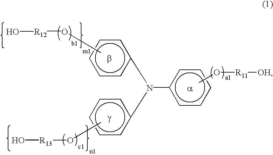
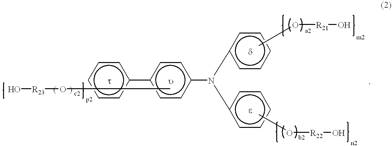
An electrophotographic photosensitive member exhibiting a good durability and stable electrophotographic performances regardless of environmental change is provided by coating the photosensitive layer with a specific protective layer. The protective layer comprises a cured phenolic resin and a charge-transporting compound having at least one group selected from the group consisting of hydroxyalkyl groups, hydroxyalkoxy groups and hydroxyphenyl groups capable of having a substituent.

Description

FIELD OF THE INVENTION AND RELATED ARTThe present invention relates to an electro-photographic photosensitive member, particularly to one characterized by having a protective layer comprising specific particles and a specific resin, and also to a process cartridge and an electro-photographic apparatus including such a photosensitive member.In recent years, extensive research and development works have been made on electrophotographic photosensitive members using organic photoconductors in view of their advantages, such as high level of safety, excellent productivity and inexpensiveness. Many proposals have been made, and many of them have been commercialized up to now.Among such photosensitive members using organic photoconductors, those using a photoconductor principally comprising a photoconductive polymer as represented by poly-N-vinylcarbazole and a charge transfer complex formed of 2,4,7-trinitrofluorene, etc., have not been necessarily satisfactory.On the other hand, a functio...

Claims


Application Information

Patent Timeline
Patent Type & Authority Patents(United States)
IPC IPC(8): G03G5/147G03G5/06
CPCG03G5/0614G03G5/1476G03G5/14708G03G5/06142G03G5/061443
Inventor NAKATA, KOUICHIMORIKAWA, YOSUKEYOSHIMURA, KIMIHIROSAITO, HIROSHI
Owner CANON KK
Why Eureka
Try Eureka