

In-situ post epitaxial treatment process
a treatment process and epitaxial technology, applied in the field of in-situ post epitaxial treatment process, can solve the problem that the nitride layer cannot be achieved through any presently available wet treatment techniqu
- Summary
- Abstract
- Description
- Claims
- Application Information
AI Technical Summary
Benefits of technology
Problems solved by technology
Method used
Image

Examples
example 1
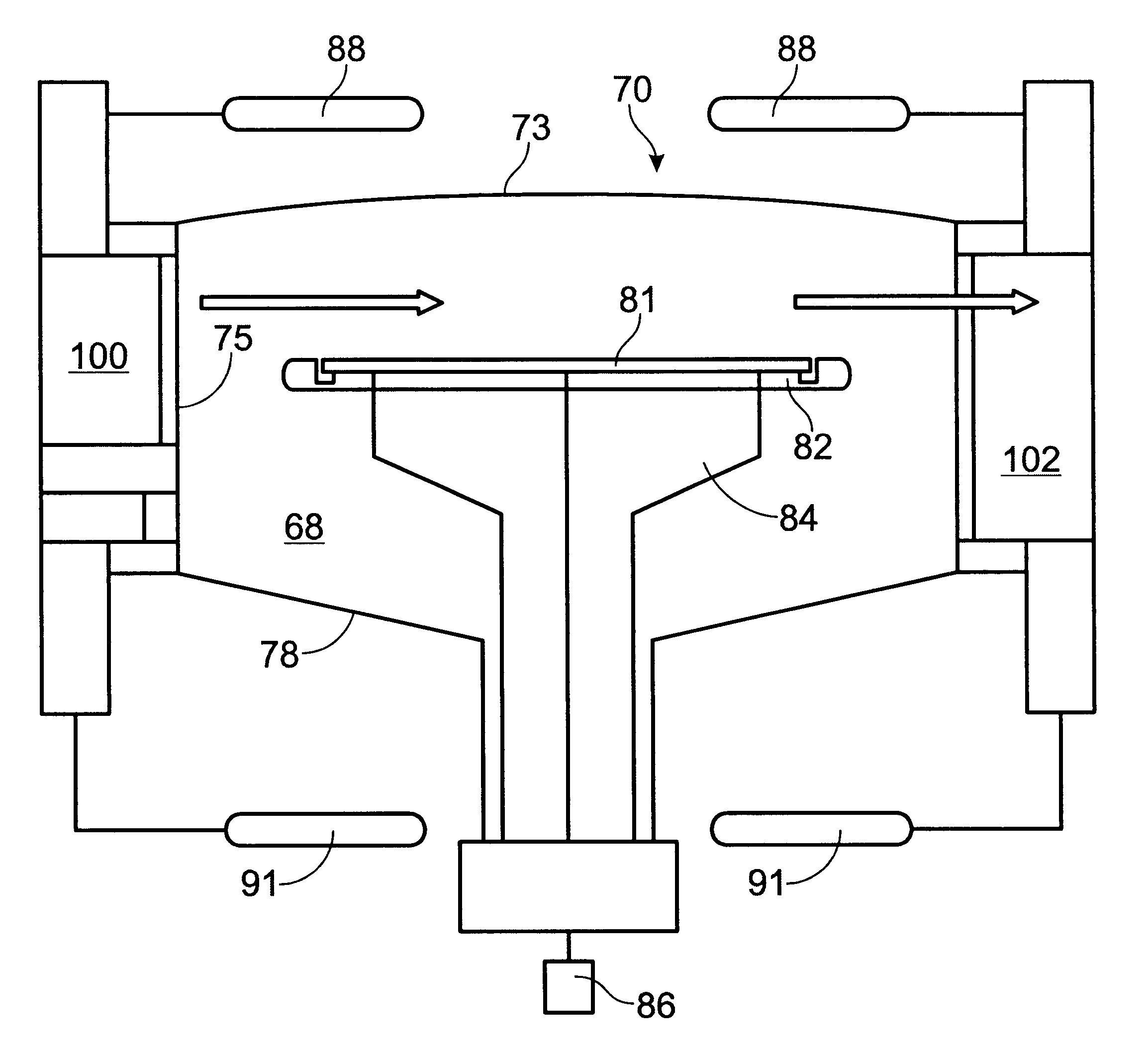
A single wafer reactor was utilized to deposit an epitaxial layer on a wafer at a temperature of 1130.degree. C. SiHCl.sub.3 was used as the reactive gas with H.sub.2 as the carrier gas. When the desired thickness of the epitaxial layer was achieved, the reactive gas supply was terminated, and the reactor was purged with H.sub.2 gas at 60 liters per minute prior to cool down for 10 seconds. At the beginning of the cool down cycle, a mixture of between 1000 and 2000 ppm O.sub.2 in Argon was introduced at 5 liters per minute while maintaining the 60 liters per minute of H.sub.2 gas flow, for 30 seconds. During this 30 second time period, the temperature was reduced to 900.degree. C. and stabilized. Wafers measured demonstrated a hydrophobic oxide layer with a thickness layer of 8 .ANG., having good oxide thickness uniformity, good haze levels, and good particle levels.
example 2
A single wafer reactor was utilized to deposit an epitaxial layer on a wafer at a temperature of 1130.degree. C. SiHCl.sub.3 was used as the reactive gas with H.sub.2 as the carrier gas. When the desired thickness of the epitaxial layer was achieved, the reactive gas supply was terminated, and the reactor was purged with H.sub.2 gas at 60 liters per minute prior to cool down for 30 seconds. At the beginning of the cool down cycle, a mixture of between 1000 and 2000 ppm O.sub.2 in Argon was introduced at 5 liters per minute while maintaining the 60 liters per minute of H.sub.2 gas flow, for 30 seconds. During this 30 second time period, the temperature was reduced to 900.degree. C. and stabilized. Wafers measured demonstrated a hydrophobic oxide layer with a thickness layer of 8 .ANG., having good oxide thickness uniformity, good haze levels, and good particle levels.
example 3
A single wafer reactor was utilized to deposit an epitaxial layer on a wafer at a temperature of 1100.degree. C. SiHCl.sub.3 was used as the reactive gas with H.sub.2 as the carrier gas was employed. When the desired thickness of the epitaxial layer was achieved, the reactive gas supply was terminated, and the reactor was purged with H.sub.2 gas at 60 liters per minute prior to cool down for 10 seconds. While maintaining the H2 gas flow, the temperature was cooled to a temperature of 1000.degree. C., wherein this temperature was maintained during the oxidation stage. A gas mixture of between 1000 and 2000 ppm O.sub.2 in Argon at 5 liters per minute was introduced into the reactor, with H.sub.2 gas flow at 60 liters per minute. The oxide deposition stage was allowed to run for 7 seconds in this constant temperature and gas, after which the O.sub.2 / Ar mixture was terminated, and the ramp down stage continued. Wafers measured demonstrated a hydrophobic oxide layer with a thickness lay...
PUM
| Property | Measurement | Unit |
|---|---|---|
| thickness | aaaaa | aaaaa |
| temperatures | aaaaa | aaaaa |
| pressures | aaaaa | aaaaa |
Abstract
Description
Claims
Application Information