

Luminescent pigments and foils with color-shifting properties
a technology of color-shifting pigments and pigments, which is applied in the field of color-shifting pigments and foils, can solve the problems of difficult use together, performance of prior color-shifting/luminescent inks, and thin film particles that do not themselves have color-shifting properties, etc., and achieves the effects of increasing the value of color-shifting pigment products, not easily duplicated, and increasing thermal stability, mechanical stability and durability
Inactive Publication Date: 2003-06-03
VIAVI SOLUTIONS INC
View PDF78 Cites 197 Cited by
- Summary
- Abstract
- Description
- Claims
- Application Information
AI Technical Summary
Benefits of technology
It is another object of the invention to provide new features for color-shifting pigments and foils that increase their value for use as security devices.
Incorporating luminescent materials into multilayer flakes also has advantages over mixtures of luminescent particles and color-shifting flakes as to the shape of the luminescent materials. These advantages principally go to the "lay down" of the flakes. In other words, the geometric positioning of the luminescent material in a flake is flat, allowing for uniform positioning and thus uniform orientation of the luminescent flakes. Also, the inherent shape of the flake can be used to control the morphology of a luminescent layer in the flake and thereby provide for new optics.
Problems solved by technology
Nevertheless, the thin film particles do not themselves have color-shifting properties.
Unfortunately, the performance of prior color-shifting / luminescent inks has several drawbacks.
The color-shifting flakes and luminescent particles also tend to be incompatible with the same ink or coating vehicle, making them difficult to use together.
Further, the luminescent particles tend to opacify and dull the color performance of the color-shifting flakes.
Additionally, the simple physical mixing of separate color-shifting and luminescent species does not allow for control of the re-emitted spectrum at differing angles since there is no way to control the optical path within simple physical mixtures.
Finally, in the current state of the art, forming a thin film interference coating structure that employs a luminescent material as the dielectric is impractical because the stoichiometry of inorganic luminescent materials is very important and their production usually requires processing at temperatures higher than standard coating temperatures.
Method used
View moreImage
Smart ImageViewing Examples

Examples
example 2
FIG. 15 is a graph illustrating the angle-sensitive emission 320 of a luminescent color-shifting pigment according to the invention. The graph illustrates how changes in the incident angle of electromagnetic energy results in different emission levels. As shown, there exists a peak 322 of maximum absorption that corresponds to a particular wavelength. Thus, a given luminescent will highly absorb at one angle of incidence but not at others. This feature of the invention allows for further customization and differentiation of luminescent color-shifting pigments and foils.
Login to View More PUM
| Property | Measurement | Unit |
|---|---|---|
| Length | aaaaa | aaaaa |
| Length | aaaaa | aaaaa |
| Thickness | aaaaa | aaaaa |
Abstract
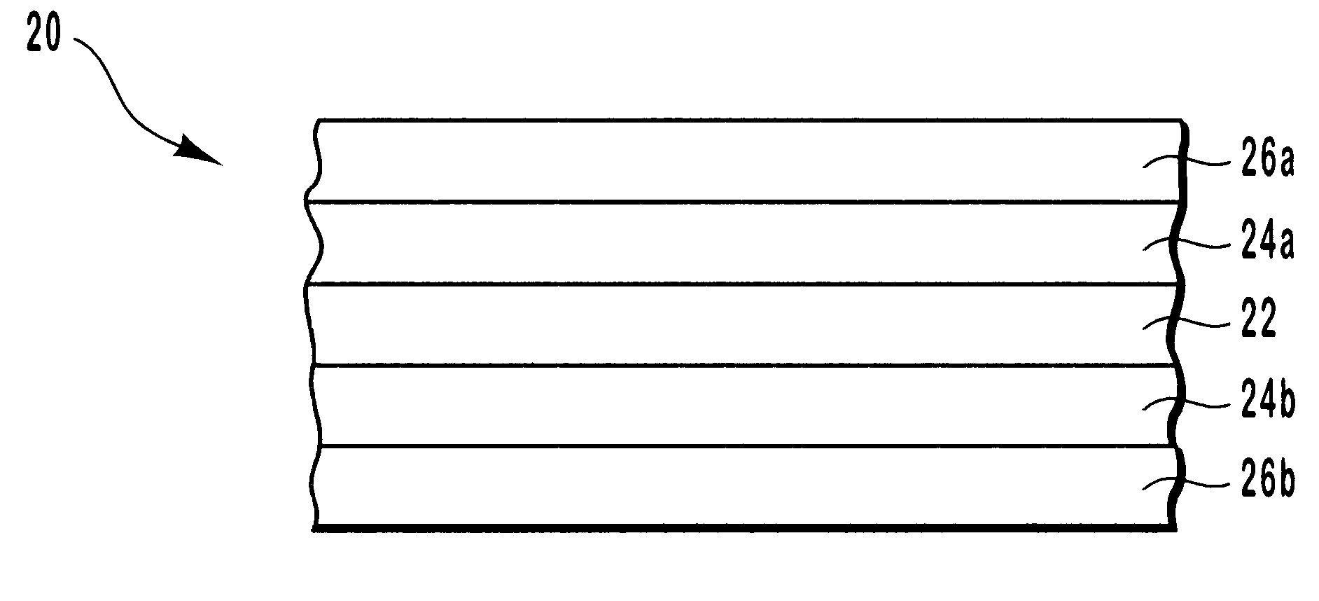
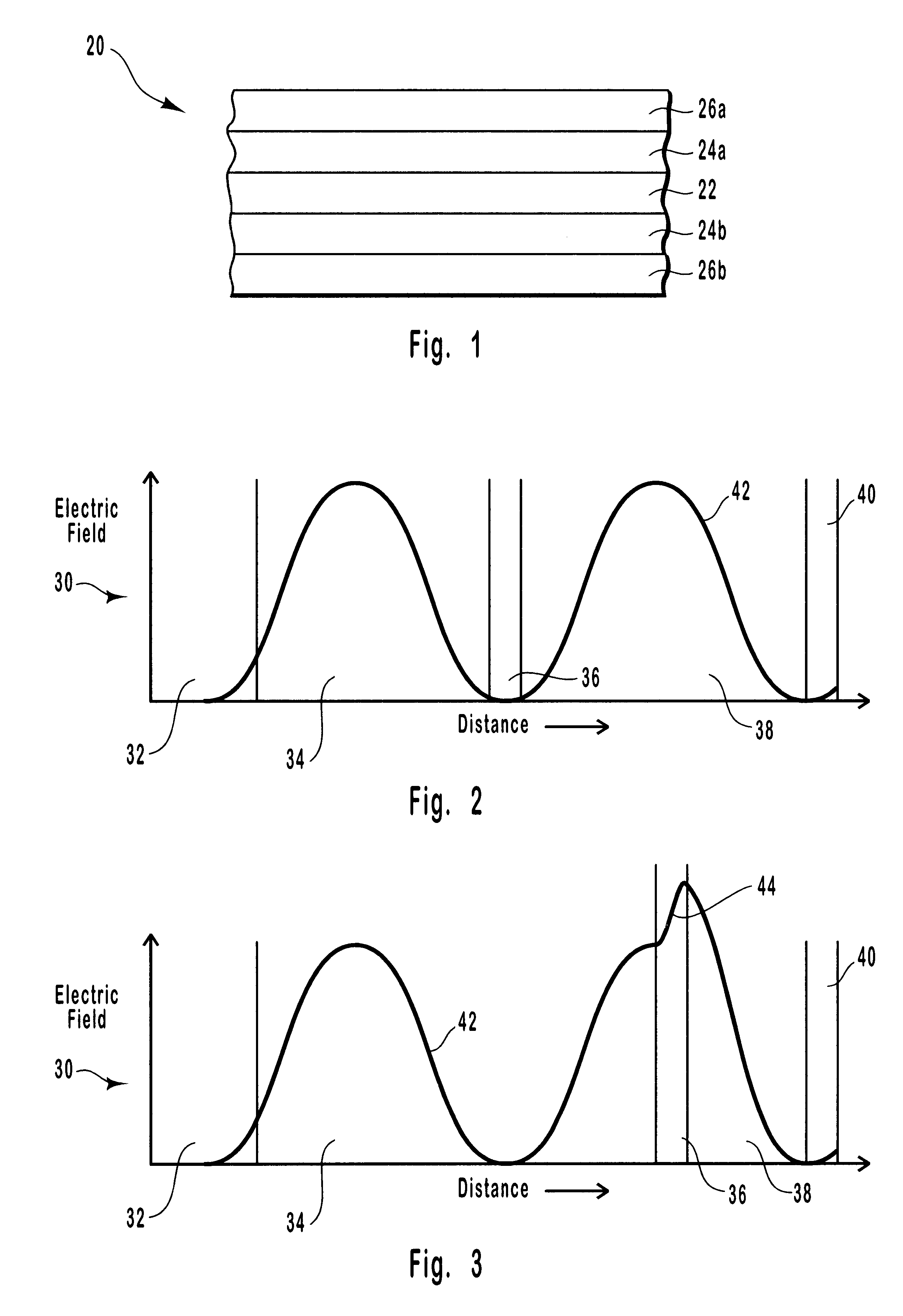
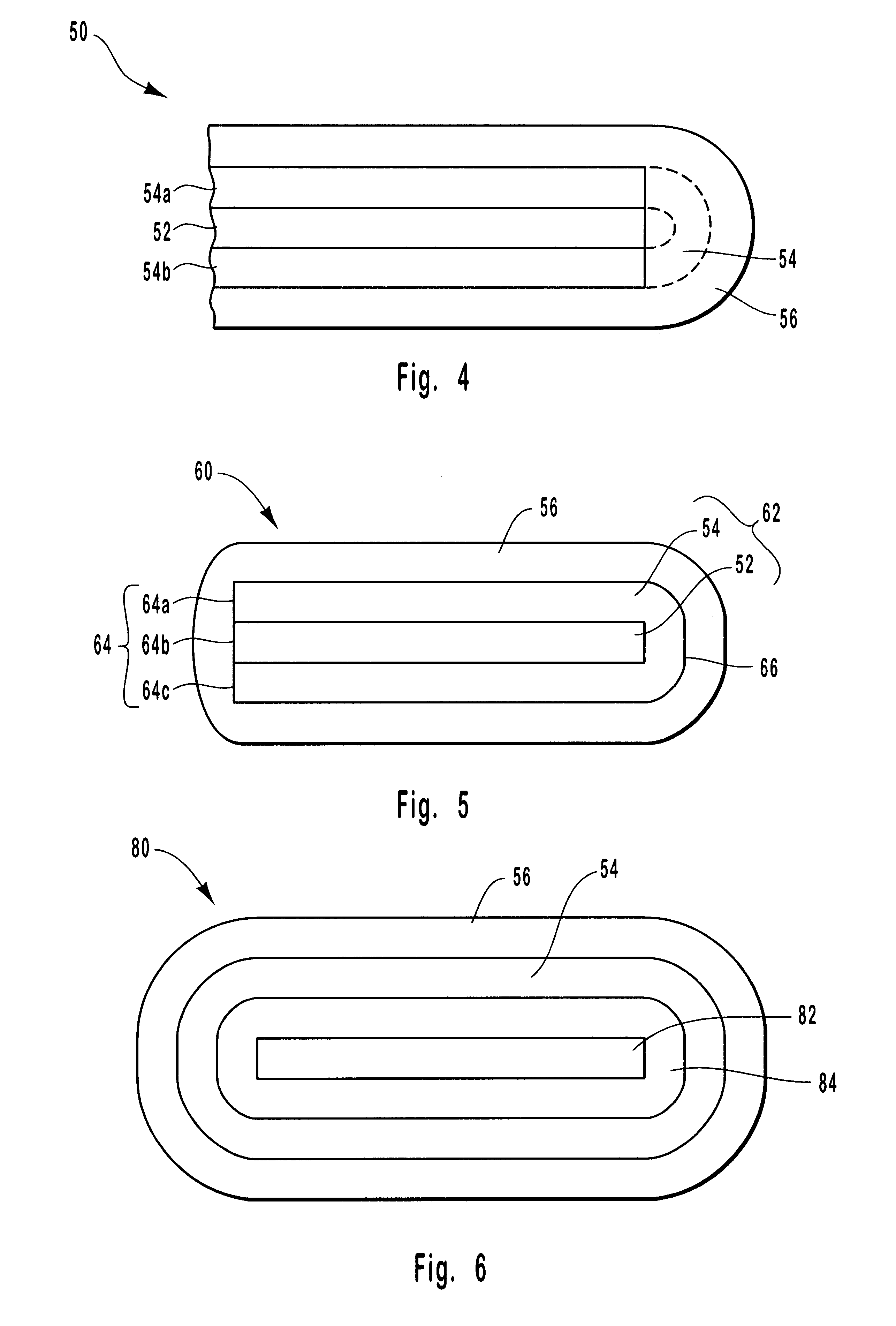
Interference pigment flakes and foils are provided which have luminescent and color-shifting properties. The pigment flakes can have a symmetrical coating structure on opposing sides of a core layer, can have an asymmetrical coating structure with all of the layers on one side of the core layer, or can be formed with encapsulating coatings around the core layer. The coating structure of the flakes and foils includes a core layer, a dielectric layer overlying the core layer, and an absorber layer overlying the dielectric layer. A luminescent material is incorporated into the flakes or foils as a separate layer or as at least part of one or more of the other layers. The pigment flakes and foils exhibit a discrete color shift so as to have a first color at a first angle of incident light or viewing and a second color different from the first color at a second angle of incident light or viewing. The pigment flakes can be interspersed into liquid media such as paints or inks to produce colorant materials for subsequent application to objects or papers. The foils can be laminated to various objects or can be formed on a carrier substrate.
Description
1. Field of the InventionThe present invention relates generally to luminescent color-shifting pigments and foils. More particularly, the present invention relates to multilayer color-shifting pigment flakes and foils which have luminescent materials incorporated therein.2. Background TechnologyVarious color-shifting pigments, colorants, and foils have been developed for a wide variety of applications. For example, color-shifting pigments have been used in applications such as cosmetics, inks, coating materials, ornaments, ceramics, automobile paints, anti-counterfeiting hot stamps and anti-counterfeiting inks for security documents and currency. Such pigments, colorants, and foils exhibit the property of changing color upon variation of the angle of incident light, or as the viewing angle of the observer is shifted.The color-shifting properties of the pigments and foils can be controlled through proper design of the optical thin films or orientation of the molecular species used to...
Claims
Login to View More Application Information
Patent Timeline
 IPC IPC(8): C09C1/00
CPCB82Y10/00B82Y30/00C09C1/0015C09C1/0081Y10T428/2991C09C2210/50C09C2220/10C09C2220/20Y10T428/2998C09C2200/1054B42D25/387B42D25/382B42D25/378C01P2004/20C01P2004/84
InventorCOOMBS, PAUL G.ZIEBA, JAROSLAWBRADLEY, JR., RICHARD A.LANTMAN, CHRISTOPHER W.MAYER, THOMASPHILLIPS, ROGER W.YAMANAKA, STACEY A.
OwnerVIAVI SOLUTIONS INC