Optical disk apparatus using tilt and aberration correction control system

Inactive Publication Date: 2003-06-10
PANASONIC CORP
View PDF10 Cites 19 Cited by
  • Summary
  • Abstract
  • Description
  • Claims
  • Application Information

AI Technical Summary

Problems solved by technology

Optical disks, however, are typically made from low rigidity materials such as polycarbonate, and even disk deflection or deformation due to warp or bending caused by the dead weight of the disk per se cannot be ignored.
In the case where original data recorded on, for example, an optical disk medium is reproduced by means of an optical pickup device, if an optical axis of an object lens of the pickup device is not perpendicular to the surface of the disk but inclined at some angle with respect to the orthogonal relationship to the surface of the disk, the beam spot projected onto the disk surface is distorted due to the aberration thereof, and there may undesirably cause a distortion in a waveform of the reproduced signal output of the optical pickup device.
Moreover, due to the aberration distortion caused in the beam spot, the reflection light beams reflected from adjacent recording pits formed on the disk undesirably interfere with each other.
Thus, the modulation degree of the reproduction signal is deteriorated, and there may be caused a shift error in a peak time (referred to as "peak shift" hereinafter) of the reproduction signal, resulting in occurrence of a discrimination error of the information reproduction (RF) signal to be a problem.
Particularly in recent years, however, the data recording density on the recording medium has been remarkably increased and distortion of the reproduction signal due to inter-code interference of the recorded data on the medium is increased, and also a noise

Method used


Image

  • Optical disk apparatus using tilt and aberration correction control system
  • Optical disk apparatus using tilt and aberration correction control system
  • Optical disk apparatus using tilt and aberration correction control system

Examples


first embodiment

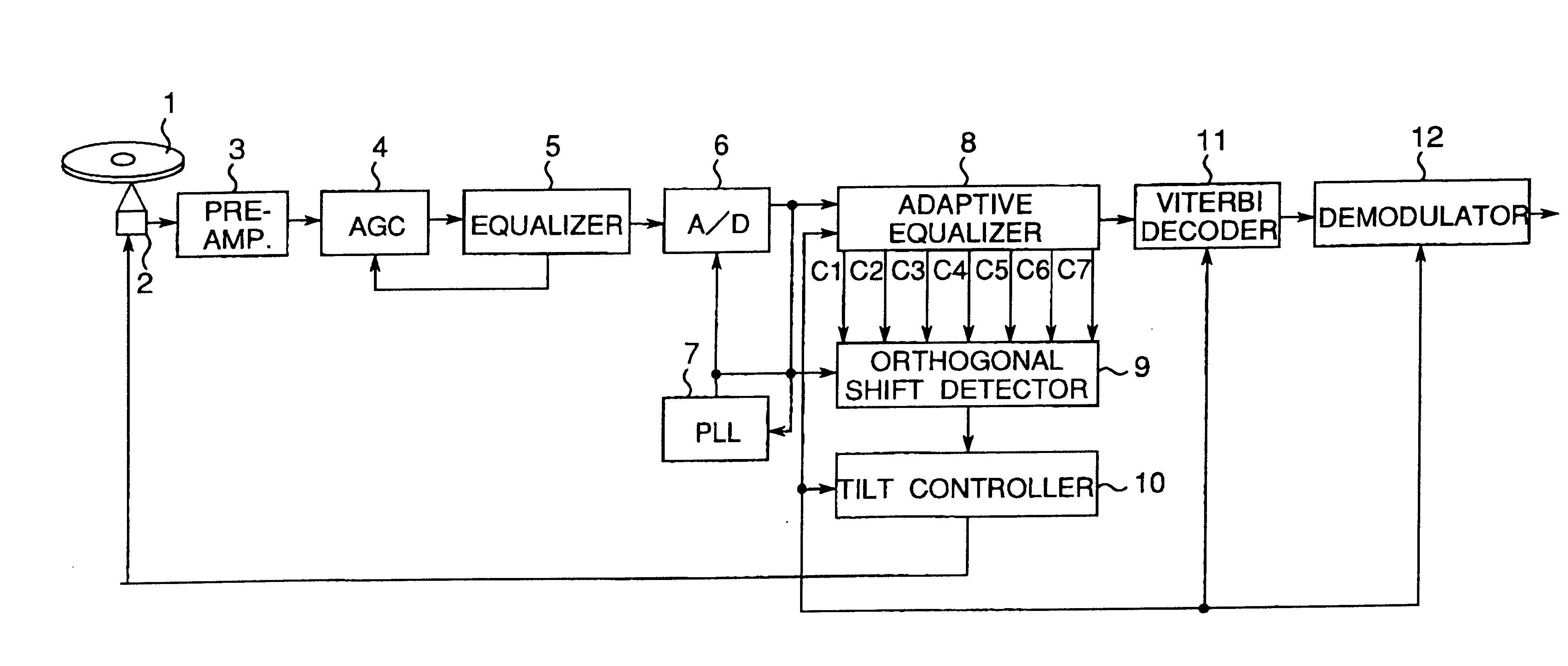
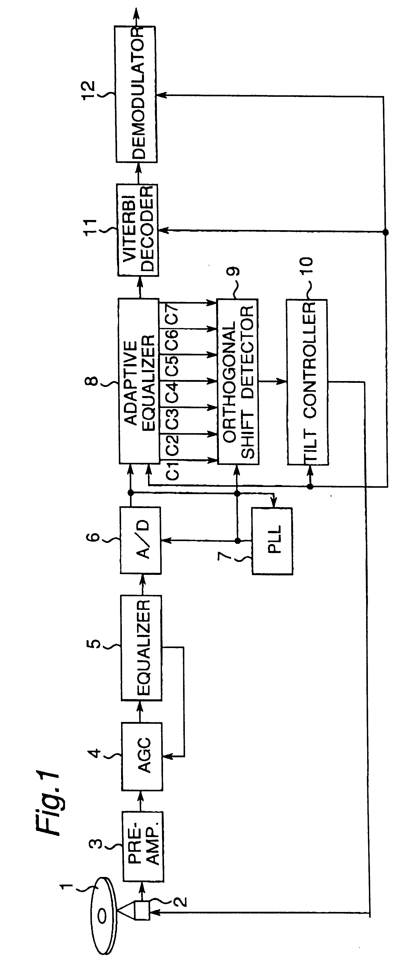
FIG. 1 shows a block construction of a data reproducing apparatus of an optical disk apparatus including a sampled amplitude read channel according to the present invention where the read channel reads a reproduction signal from a disk medium and generates binary data therefrom, including an adaptive equalizer in a digital data reproducing apparatus. In this construction, an optical disk 1 is used as an example of a disk medium which has a sector format of a periodically wobbling recording groove. An optical pickup device 2 applies laser beams to the optical disk and reads the recorded data based on the quantity of the reflected light beams and generates an electric signal therefrom. A preamplifier 3 amplifies the output signal of the pickup device and generates a reproduction RF signal.

The read channel of the data reproducing apparatus includes an auto-gain controller (AGC) 4 for adjusting an amplitude of the reproduction signal to have a constant amplitude, an equalizer 5 for impr...

second embodiment

FIG. 10 shows a block construction of a data reproducing apparatus according to a second embodiment of the present invention. The different points from the first embodiment reside in the fact that, aberrration correction is performed instead of performing a tilt control in the track tangential direction of the optical disk, using a liquid crystal aberration correction unit instead of using the tilt actuator in the optical pickup 2, using an aberration detector 13 instead of using the orthogonal shift detector 9, and using an aberration controller 14 instead of using the tilt controller 10, thereby constituting an aberration correcting system for correcting an aberration distortion due to an orthogonal shift and the like of a beam spot projected onto a recording surface of the disk to obtain a preferable reproduction signal waveform.

FIG. 11 shows a construction of an optical pickup 2' in the optical disk apparatus of the second embodiment, where 2a denotes an object lens and 2h denot...

third embodiment

FIG. 14 shows a block construction of an optical disk apparatus according to the third embodiment of the present invention. In this embodiment, the tilt control system of the first embodiment as shown in FIG. 1 is employed, and a different point therefrom is that a system controller (control CPU) 15 is further provided for controlling the adaptive equalizer 8, orthogonal shift detector 9, tilt controller 10 and optical pickup device 2 to consntitute a data recording and reproducing apparatus. It is noted here that FIG. 14 mainly shows the construction of the disk reproducing system, omitting the construction of the disk recording system here since the disk recording system is already described with reference to FIG. 19.

FIGS. 15A through 15G show timing charts in connection with a sector format of a recording guide groove formed on e.g. a DVD-RAM as a disk medium, where FIG. 15A shows a disk sector format, each sector is comprised of a prepit address region 61 formed of emboss prepit...


PUM


Abstract

A tilt control apparatus includes an orthogonal shift detector (9) which detects an orthogonal shift by comparing a pair of a plurality of tap coefficients (C1, . . . , C7) of a FIR filter and generates an orthogonal shift signal, and an actuator varies the inclination of the optical axis of the light beam to correct the orthogonal shift, and a tilt controller (10) controls the drive of the actuator in accordance with the orhogonal shift signal to minimize the orthogonal shift. In the information recording operation, the orthogonal shift obtained based on a recording track is previously stored in a temporary storage portion and the stored orthogonal shift is used to conduct the tilt control.

Description

1. Field of the InventionThe present invention generally relates to an optical disk apparatus for recording and / or reproducing information to and / or from an optical disk, and in particular to an optical disk apparatus having an aberration or tilt correction control system for maintaining an orthogonal relationship between an optical axis of a light beam projected by an optical pickup device and an information recording surface of the optical disk.2. Description of the Prior ArtHigh speed random access is possible with disc-shaped recording medium, and a high recording density can be achieved by formatting a disk with a narrow data track pitch and pit pitch.Optical disks such as a DVD, which is typical, have been widely used in recent years as a large capacity recording medium because of a high recording density. Further advances in recording density have also been achieved to further increase storage capacity. Optical disks, however, are typically made from low rigidity materials su...

Claims


Application Information

Patent Timeline
IPC IPC(8): G11B7/00G11B7/005G11B7/09G11B7/095G11B7/135
CPCG11B7/0945G11B7/0956G11B20/10481G11B7/13927G11B20/10046G11B20/10212G11B7/1369G11B7/0053G11B7/0941
Inventor KONISHI, SHINICHINAKAJIMA, TAKESHI
Owner PANASONIC CORP
Why Eureka
Try Eureka