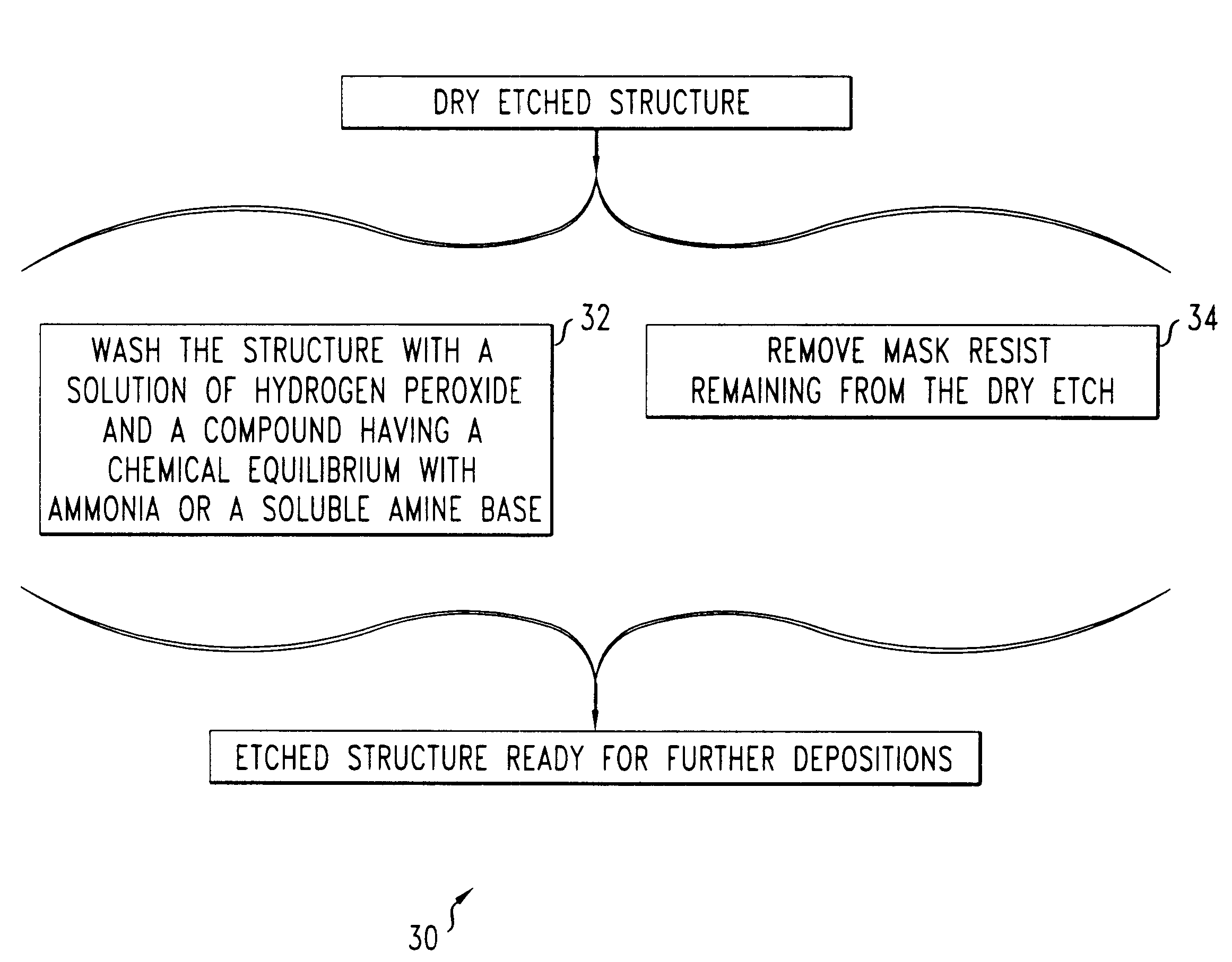
Removal of metal veils from via holes
a metal veil and via hole technology, applied in the preparation of detergent mixtures, inorganic non-surface active detergent compositions, detergent compounding agents, etc., can solve the problems of preventing the subsequent formation of high-quality electrical contacts in via holes, affecting the contact resistance of via holes, and affecting the effect of the metal veil collaps
- Summary
- Abstract
- Description
- Claims
- Application Information
AI Technical Summary
Benefits of technology
Problems solved by technology
Method used
Image

Examples
Embodiment Construction
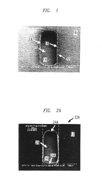
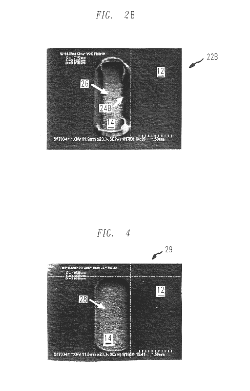
FIG. 1 is a top view of an intermediate ICD or MEOD structure 8 that has a hole 10. The via hole 10 was made by performing inductively coupled plasma (ICP)-reactive ion etch (RIE) through a dielectric layer and stopping the ICP-RIE on an underlying metal layer 14. The dielectric layer includes polymerized benzo cyclobutene and is covered by an overlying layer 16 of mask resist. The underlying metal layer 14 is a multi-layer that includes, i.e., from top-to-bottom, a 5 nanometer (nm) thick palladium (Pd) cap, a 35 nm thick layer of platinum (Pt), a 650 nm thick layer of gold (Au), and a 40 nm thick layer of Pd.
During the ICP-RIE, reactive ions sputtered heavy metal atoms out of top layers of metal layer 14. A portion of the sputtered heavy metal atoms have produced porous metal veil 18, i.e., a thin layer. The metal veil 18 lines vertical walls 20 of the hole 10, which traverses both a dielectric layer and the layer 16 of mask resist. The metal veil 18 is fragile and only weakly atta...
PUM
| Property | Measurement | Unit |
|---|---|---|
| thick | aaaaa | aaaaa |
| thick | aaaaa | aaaaa |
| thick | aaaaa | aaaaa |
Abstract
Description
Claims
Application Information
 - R&D
- Intellectual Property
- Life Sciences
- Materials
- Tech Scout
- Unparalleled Data Quality
- Higher Quality Content
- 60% Fewer Hallucinations
Browse by: Latest US Patents, China's latest patents, Technical Efficacy Thesaurus, Application Domain, Technology Topic, Popular Technical Reports.
© 2025 PatSnap. All rights reserved.Legal|Privacy policy|Modern Slavery Act Transparency Statement|Sitemap|About US| Contact US: help@patsnap.com