Apparatus and method for monitoring a structure using a counter-propagating signal method for locating events

a counter-propagating signal and apparatus technology, applied in the direction of optical apparatus testing, optical radiation measurement, instruments, etc., can solve the problems of inability to monitor engineered structures in real-time, requiring a large number of sensors, and the subsequent cost and complexity of such a system are most often impractical

Inactive Publication Date: 2003-09-16
FUTURE FIBRE TECH PTY LTD
View PDF16 Cites 59 Cited by
  • Summary
  • Abstract
  • Description
  • Claims
  • Application Information

AI Technical Summary

Benefits of technology

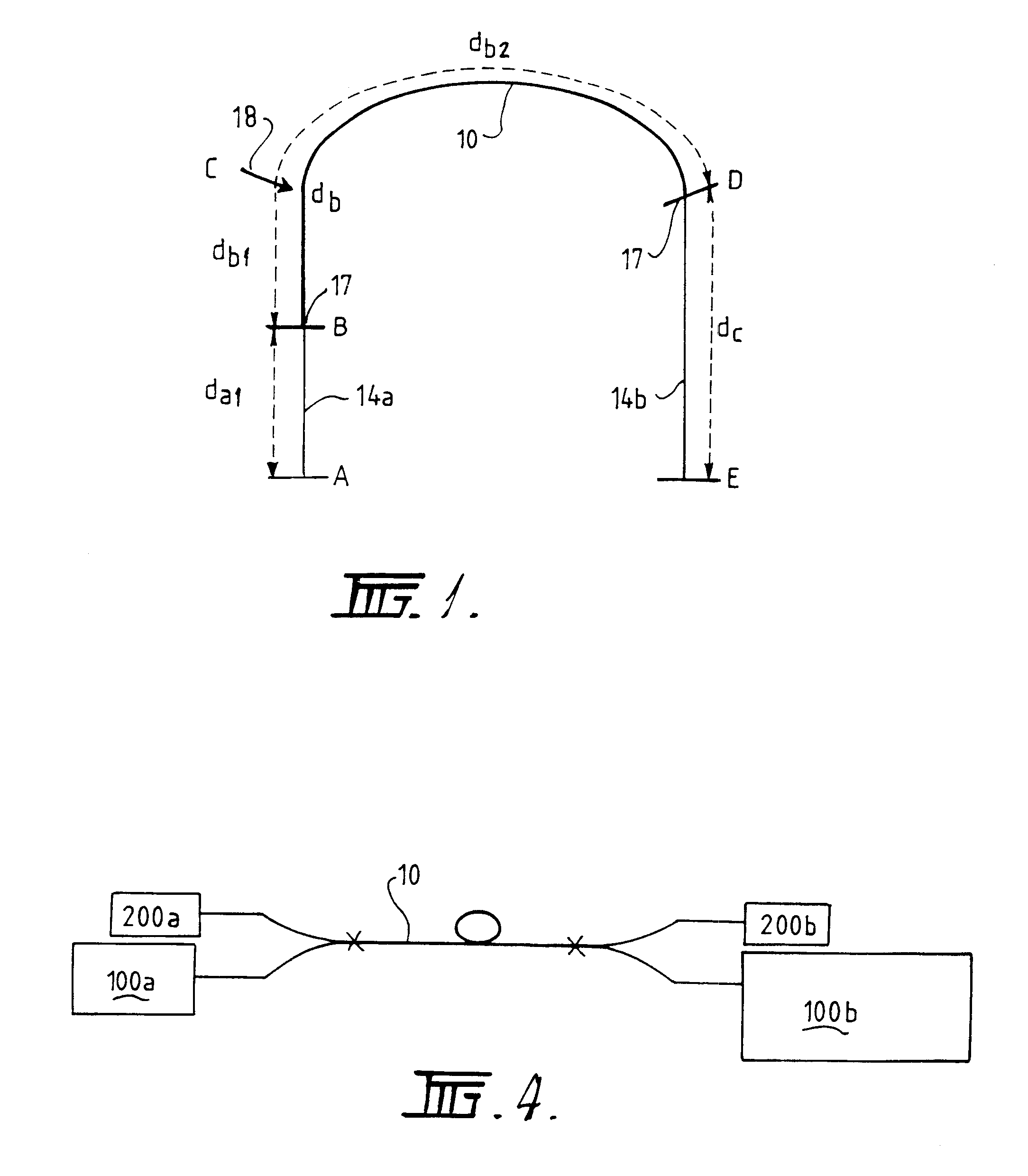
The present invention relies on the measurement of the time delay or difference between transmissive counter-propagating optical signals affected by the same event. In this novel arrangement, optical signals, preferably continuous-wave (CW) optical signals, are launched, preferably from a single light source, into the waveguide and simultaneously detected by a detector such as two separate photodetectors. Pulsing of the optical signal is not necessary, although it may be employed in some arrangements. Any sensed parameter which acts to alter the counter-propagating signals will effect both signals in the same manner, but because the effected counter-propagating signals must each continue travelling the remainder of the waveguide length to their respective photodetectors there is a resultant time delay or time difference between the detected signals. The time delay is directly proportional to the location of the sensed event along the waveguide length. Therefore, if the time delay or difference is detected and measured, the location of the event can be determined. At the same time, if a compatible sensing mechanism is being employed the sensed event can be quantified and / or identified (ie., strain, vibration, acoustic emission, temperature transient, etc.). In addition, non-sensitive fibre optic delay lines may be connected to the waveguide at either or both ends in order to add additional delay between the transmissive counter-propagating signals and to provide insensitive lead fibres. This may assist engineering the technique into a practical working system.
The invention also has the advantage of operating on virtually any existing type of transmissive distributed fibre optic sensor, enabling dynamic and transient events to be detected, quantified and located anywhere along the length of the optical fibre which forms the waveguide. Furthermore, it operates in a transmissive configuration, thus, delivering substantially the entire optical signal and power back to the detector and not requiring signal averaging, and it determines the location of events via the time delay measurement between counter-propagating optical signals effected by the same disturbance.
Preparing or connectorising the free ends of the fibre leads in any manner which facilitates attaching, connecting, splicing or coupling the fibre leads to the appropriate combination and arrangement of light source, couplers, photodetectors and signal processing electronics which achieves the transmissive counter-propagating signal method for locating events in optical waveguides.
In an alternate arrangement, the sensor fibre may be replaced by two or more suitably configured optical fibres (single or multi moded) and additional couplers may be utilised to connect the plurality of sensor fibres to the fibre optic leads. In this arrangement, a further number of couplers and photodetectors may be required at the instrumentation to facilitate the increased number of sensing and lead fibres.
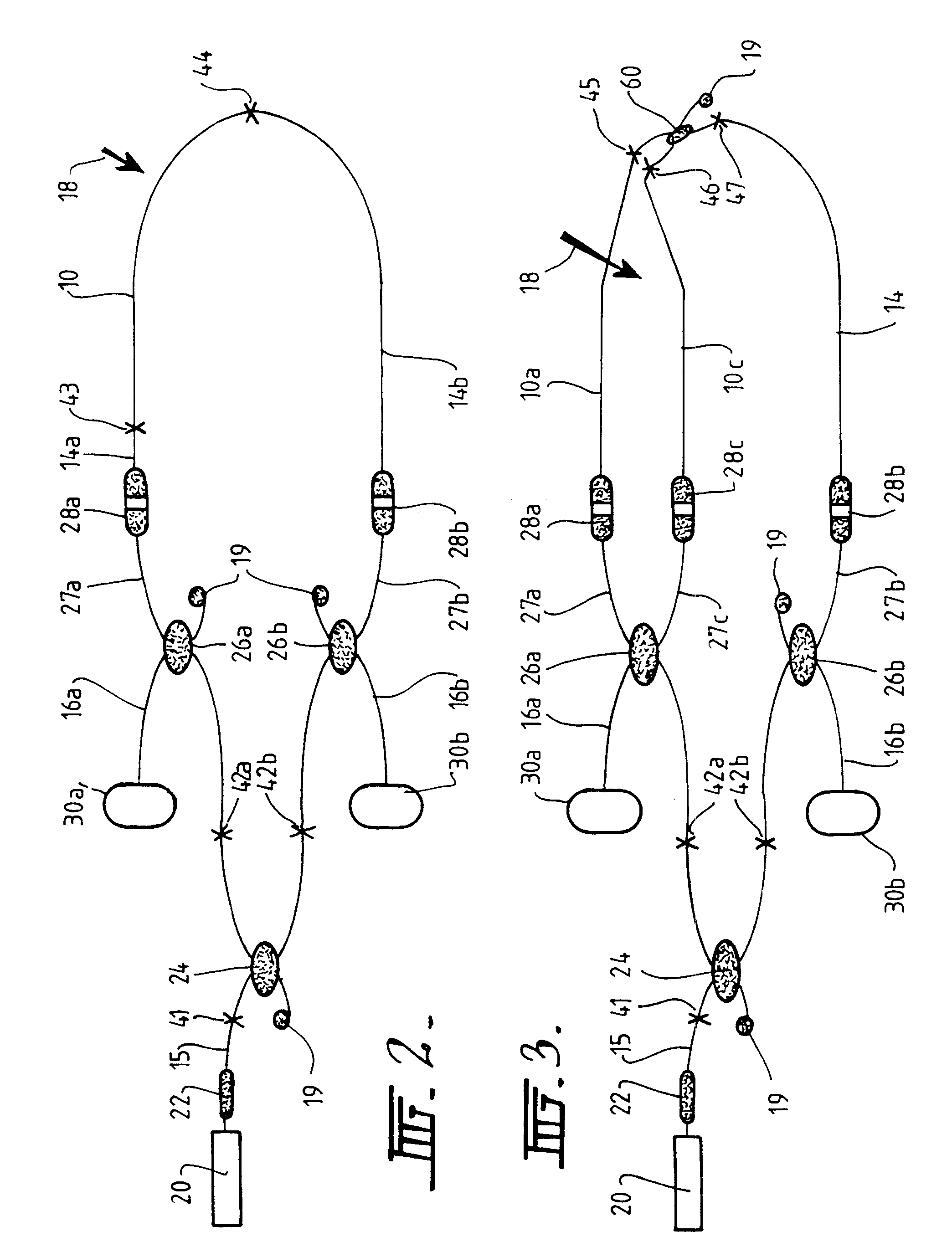
In the method, according to the preferred embodiment of the invention, electromagnetic radiation is launched into an optical waveguide (single or multi moded), such as an optical fibre, from a light source, such as a pigtailed laser diode, fibre laser or light emitting diode, and propagates along the optical waveguide. The optical waveguide is connected (temporarily or permanently) to one arm of an optical waveguide light splitter or coupler and when the electromagnetic radiation reaches the light splitter the electromagnetic radiation can branch out into the two output waveguide arms of the light splitter. Each of the output arms of this light splitter are fusion spliced to other couplers, thus the optical radiation from the laser source is simultaneously launched into each of the other two couplers. These two couplers form the launch and detection ports for the dual-ended, counter-propagating method described above. The optical signal is simultaneously launched to the output waveguide arms of the couplers. Only one output arm is used in each coupler, the other is fractured or otherwise terminated to avoid back-reflections. The output arms of the couplers are either connected (temporarily or permanently) directly to the waveguide sensing element or to a lead optical waveguide which is connected (temporarily or permanently) to the waveguide sensing element. Any one of the output waveguide arms of the light splitter may be used to deliver the electromagnetic radiation to the sensor waveguide via an optical waveguide lead. Likewise, a plurality of output waveguide arms may be used to deliver the electromagnetic radiation to a number of individual or multiplexed waveguide sensors. Each of the counter-propagating signals transmitted into the waveguide sensor propagates along the entire length of the waveguide until they reach the opposite ends and are launched back into the latter couplers in the opposite direction to the initial launch signals. The signals are each split in the reverse direction through the latter couplers. Part of the signals travel back towards the first coupler and laser, and the remainder of the signals travel along the unused arms of the latter couplers, which are terminated at photodetectors. The optical signals are simultaneously monitored by the two photodetectors. Appropriate electronics, signal processing schemes and algorithms process the signals from each detector and provide the location of the sensed event by determination of the time delay or difference between the signals effected by the same disturbance. The insensitive fibre optic leads may be very long to provide an additional time delay between the optical signals. This may assist engineering the technique into a practical working system.

Problems solved by technology

Engineered structures are usually not monitored in real-time because of the difficulties in incorporating conventional sensors into the sensing environment and because of the limitations of the sensors.
Furthermore, conventional sensors are generally point sensing devices, thus requiring a large number of sensors to cover a large area or long length of interest.
The subsequent cost and complexity of such a system is most often impractical.
However, to-date most fibre optic sensor systems are based on point sensing devices, thus again requiring a large number of sensors to cover a large area or long length.
Various OTDR back-scattering techniques for strain and pressure measurements have also been investigated, although no commercial technology is yet available.
However, while modern advances in photonics devices have allowed very precise and accurate systems to be developed and commercialised, they are often very complex and expensive.
Owing to the requirement of measuring and averaging the time-of-flight of very narrow, low power pulses, these techniques are often limited to monitoring static or very slowly varying parameters.
Any sensed parameter which acts to alter the counter-propagating signals will effect both signals in the same manner, but because the effected counter-propagating signals must each continue travelling the remainder of the waveguide length to their respective photodetectors there is a resultant time delay or time difference between the detected signals.
The insensitive fibre optic leads may be very long to provide an additional time delay between the optical signals.

Method used


Image

  • Apparatus and method for monitoring a structure using a counter-propagating signal method for locating events
  • Apparatus and method for monitoring a structure using a counter-propagating signal method for locating events
  • Apparatus and method for monitoring a structure using a counter-propagating signal method for locating events

Examples


example

Location of Point of Disturbance Using the Modalmetric Effect

It has long been known that when a multimode optical fibre is disturbed, the distribution of the modes is affected. This modulation of the modal distribution in a multimode fibre is known as the modalmetric effect. The modalmetric effect in a multimode fibre can be used to sense and monitor vibrations, disturbances or movement of the fibre itself, or any structure or object the fibre is attached to, by detecting an intensity change in the speckle pattern output of the fibre. Modalmetric sensors can therefore be used as vibration sensors in structural monitoring, condition monitoring of high voltage equipment, intrusion detection of cables or pipelines, and in fence perimeter security.

Initially, optical fibres were deployed mainly in long-haul and high-speed telecommunication systems. However, with the decrease in cost of optical fibre cable, and optoelectronic sources and detectors, optical fibres are now being used as the...


PUM

PropertyMeasurementUnit
lengthaaaaaaaaaa
lengthaaaaaaaaaa
refractive indexaaaaaaaaaa

Abstract

A method and apparatus for monitoring a structure and for locating the position of an event including a light source, a waveguide, and a detector means. The waveguide receives light from the light source so that the light is caused to propagate in counter-propagating optical signals in the waveguide. The waveguide includes the counter-propagating optical signals or some characteristic of the signals modified or effected by an external parameter caused by or indicative of the event to provide modified counter-propagating optical signals. The detector means detects the modified counter-propagating optical signals effected by the parameter and determines the time delay or difference between the modified counter-propagating optical signals in order to determine the location of the event.

Description

This invention relates to an apparatus and method for monitoring a structure which employs a waveguide transmissive counter-propagating signal method and associated systems for locating events in fibre optic sensing systems.The term "structure" used in this specification and in the claims should be understood to mean machines, buildings, infrastructure such as pipe lines and the like to which the apparatus and method may be applied as well as waveguides themselves which act as a communication link for transmission of data from one place to another.It should also be understood that the term "light" used in the specification and claims means both visible and non-visible parts of the electromagnetic radiation spectrum.ART BACKGROUNDOptical devices are commonly used in industry and science and include laser cavities, waveguides, lenses, filters and other optical elements and their combinations. Such optical devices are used in a variety of instruments and installations.Photonics technol...

Claims


Application Information

Patent Timeline
Patent Type & Authority Patents(United States)
IPC IPC(8): G01M11/00G01M5/00G01M99/00G01B11/00G01N21/63
CPCG01M5/0025G01M5/0041G01M5/0091G01M11/083G01M11/3109G01M11/39G01N21/63
Inventor TAPANES, EDWARD EGOODE, JASON RKATSIFOLIS, JIM
Owner FUTURE FIBRE TECH PTY LTD
Why Eureka
Try Eureka