Production of a dense mist of micrometric droplets in particular for extreme UV lithography

Inactive Publication Date: 2003-11-11
COMMISSARIAT A LENERGIE ATOMIQUE ET AUX ENERGIES ALTERNATIVES
View PDF16 Cites 47 Cited by
  • Summary
  • Abstract
  • Description
  • Claims
  • Application Information

AI Technical Summary

Benefits of technology

This invention divulges a technique for the generation of EUV radiation that has almost all the advantages of known techniques mentioned above, without the disadvantages of these known techniques.

Problems solved by technology

Secondly, the average density of the target must be sufficiently large.
This leads to the generation of solid debris originating from erosion of the nozzle.
Furthermore, the local density of atoms in each aggregate is very high, such that a large number of atoms participate.
Furthermore, the large number of aggregates comprising a sufficiently high average number of atoms within the laser beam focusing area results in a very strong emission in the extreme ultraviolet.
However, large quantities of material debris can be produced by erosion of the nozzle when it is placed too close to the illuminated area.
Operation at high frequency (of the order of 1 kHz) requires high gas flows and consequently very powerful pumping means that could induce vibrations harmful to the alignment of the optics for a lithography apparatus comprising the aggregate generation device.
This is why excitation by the laser beam must take place in the immediate vicinity of the nozzle which causes severe erosion of this nozzle (which is usually metallic) by the impact of ions output from the plasma.
Erosion of the nozzle significantly reduces its life and therefore the reliability of the EUV radiation source and generates large quantities of debris that could deteriorate the optics and the mask of the lithography apparatus.
These micro-crystals are too large for penetration of the excitation laser beam to be complete, unlike what happens with xenon aggregates.
Therefore, the technique described in document [2] does not satisfy the criteria for obtaining a sufficiently intense EUV radiation source.
This type of target also has the disadvantage that it does not contain enough material to have a sufficiently large number of potential EUV emitters.
Furthermore, the sources described in documents [2] and [3] are not very stable in terms of intensity.
In the case described in document [2], it is difficult to irradiate each ice micro-crystal in the same manner due to a problem of synchronisation with the laser.
The result is a significantly lower production of EUV radiation.
Therefore, there is a large content of superfluous gas at high frequency that has to be pumped, which causes vibrations as in the case of jets of xenon aggregates.

Method used


Image

  • Production of a dense mist of micrometric droplets in particular for extreme UV lithography
  • Production of a dense mist of micrometric droplets in particular for extreme UV lithography
  • Production of a dense mist of micrometric droplets in particular for extreme UV lithography

Examples


Embodiment Construction

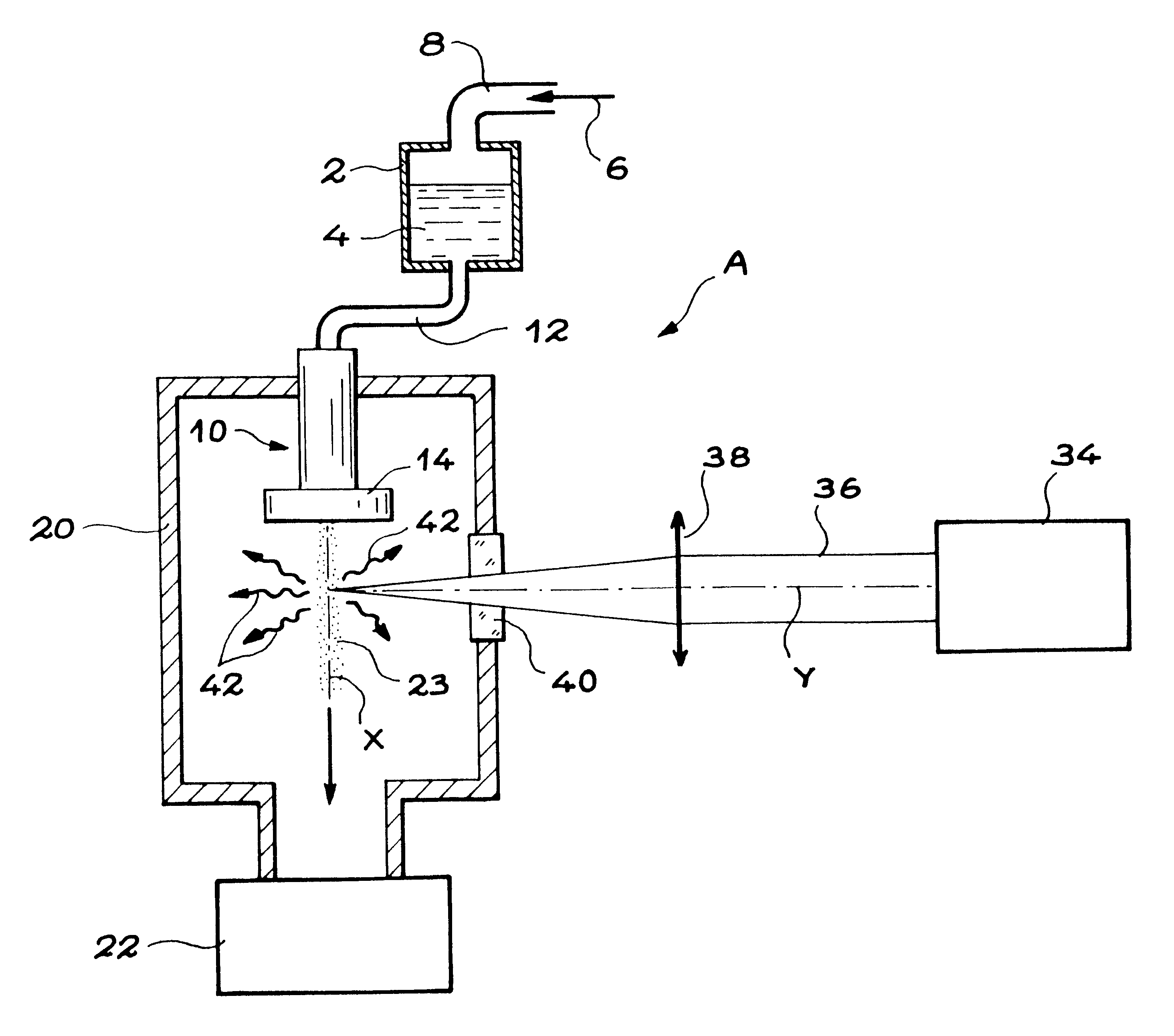
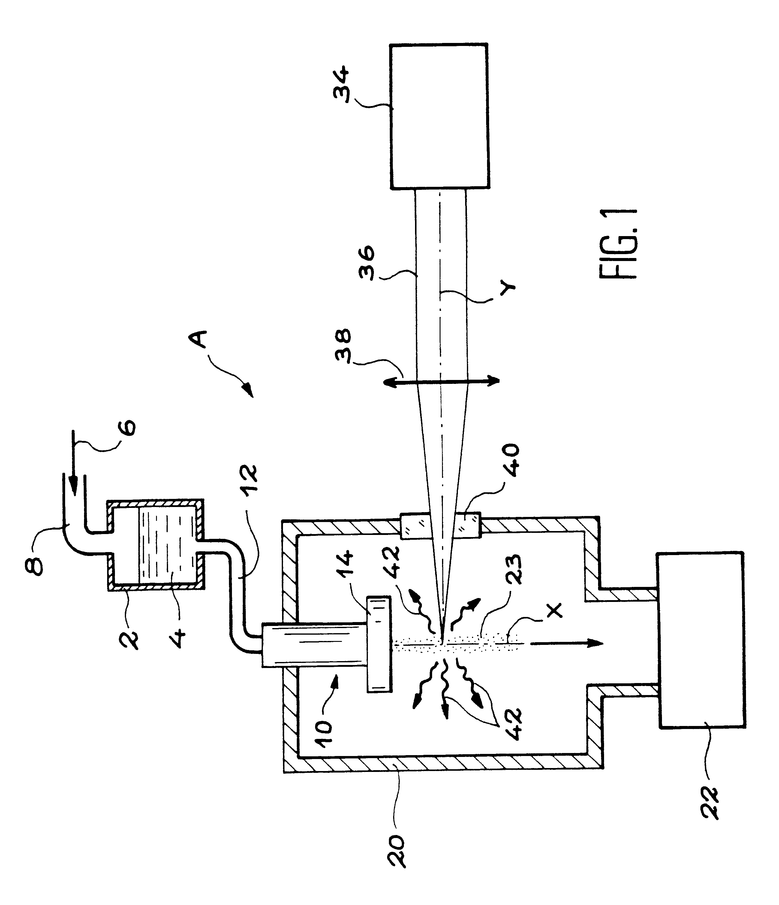
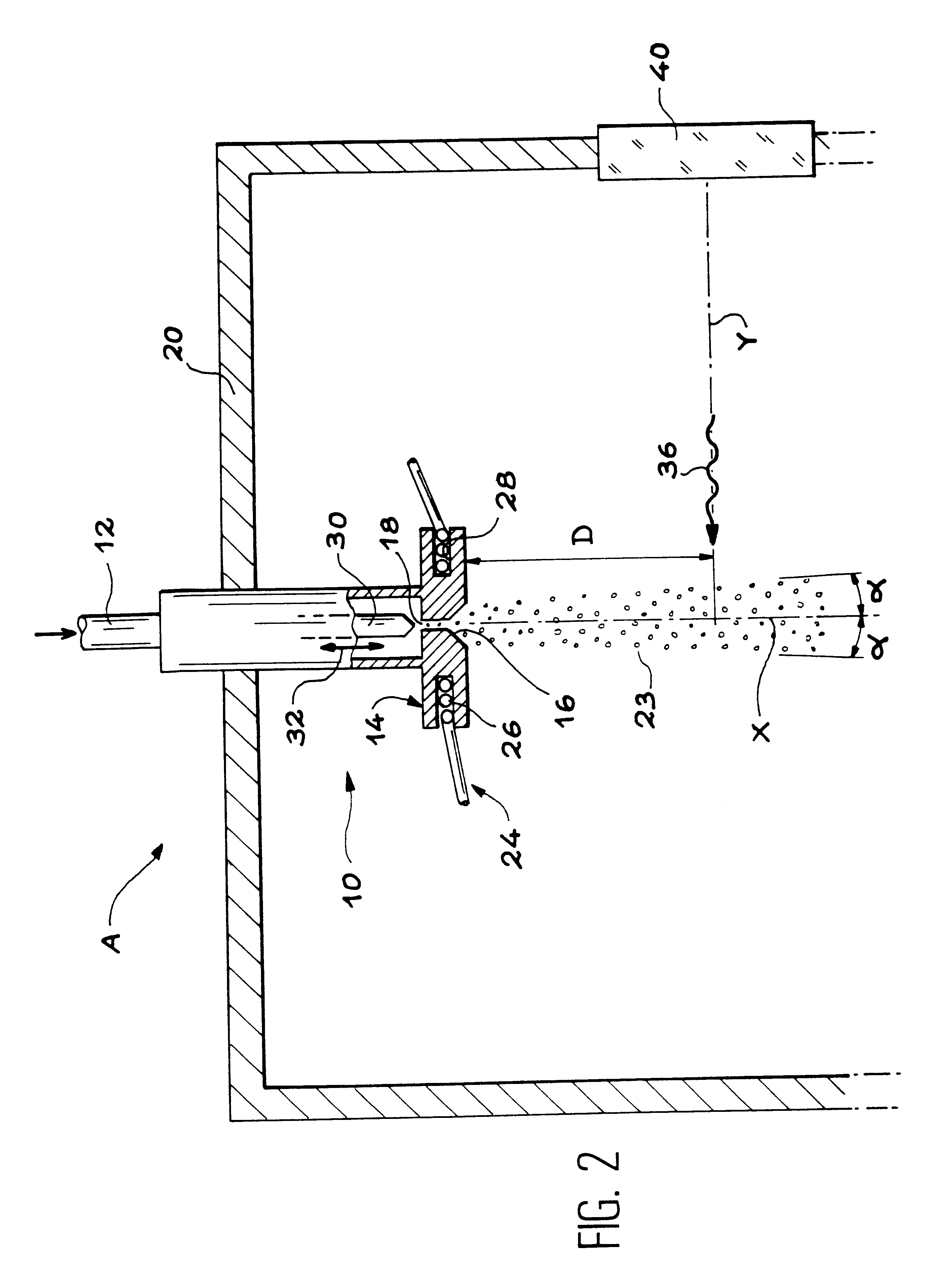
The fog generation device A according to the invention that is shown diagrammatically in FIG. 1, and part of which is shown diagrammatically in FIG. 2 comprises a reservoir 2 that is designed to contain a liquid 4 that will be used to generate a dense fog of micrometric and submicrometric droplets.

The device A also comprises means of pressurization of the liquid 4 contained in the reservoir 2. These pressurization means are symbolized by the arrow 6 in FIG. 1 and, in the example shown, are designed to send a pressurized gas into the reservoir.

This pressurized gas, derived from means not shown, is an inert gas for example such as air, nitrogen or argon.

The pressure in this gas that is applied to the liquid is equal to 5.times.10.sup.5 Pa to 10.sup.7 Pa.

The pressurized gas is directed to the upper part of reservoir 2 through a pipe 8.

The device A conform with the invention also comprises a nozzle 10 that leads to the bottom of the reservoir 2 through a pipe 12. For example, this nozzl...


PUM


Abstract

Process and device for the generation of a fog of micrometric and submicrometric droplets, which may find application to the generation of light in the extreme ultraviolet range, particularly for lithography. According to the process and device, a pressurized liquid is injected into a very small diameter nozzle opening up into a vacuum. Light is generated by focusing laser radiation onto the fog.

Description

This invention relates to a process and a device for the generation of a dense fog of micrometric and submicrometric droplets.In particularly, it is applicable to the generation of extreme ultraviolet radiation also called "EUV radiation".It is radiation with a wave length within the range between 8 and 25 nanometers.The EUV radiation produced according to this invention has many applications, particularly in science of materials, microscopy and particularly lithography, to make integrated circuits with a very large scale integration (VLSI).Other applications include the surface deposition of aggregates, for which large and hot aggregates are more suitable than small and cold aggregates generated by all devices according to prior art.STATE OF PRIOR ARTMany techniques are known for the production of EUV radiation, for example techniques consisting of using a laser beam to irradiate a target placed in a vacuum.When the illumination from the laser beam is sufficiently intense, the targ...

Claims


Application Information

Patent Timeline
IPC IPC(8): G03F7/20H05G2/00B05B1/00B05B17/00G21K5/02G21K5/08G21K7/00H01L21/027
CPCG03F7/70033H05G2/003H05G2/008Y10S977/951Y10S977/887B05B7/32
Inventor SCHMIDT, MARTINSUBLEMONTIER, OLIVIER
Owner COMMISSARIAT A LENERGIE ATOMIQUE ET AUX ENERGIES ALTERNATIVES
Why Eureka
Try Eureka