Gas turbine seal

a technology of gas turbine and seal, applied in the direction of machines/engines, stators, liquid fuel engines, etc., can solve the problems of wear and other damage to components, the possibility of relatively small layer thickness, and the cost increas

Inactive Publication Date: 2003-11-25
GENERAL ELECTRIC TECH GMBH
View PDF12 Cites 59 Cited by
  • Summary
  • Abstract
  • Description
  • Claims
  • Application Information

AI Technical Summary

Benefits of technology

An advantage in this respect is that with the gas turbine seal according to the invention high ceramic layer thicknesses of up to approx. 20 mm are achieved, these layers having a good bond strength, and the ceramic not being flaked away even in the event of the introduction of radial / tangential forces, sickle-shaped contact or locally high overheating / frictional heat, and a good sealing action being achieved.
Moreover, the use of rivets as a bond layer has the effect of forming a continuous ceramic network with individual metal islands, which has a positive effect on the properties of the layer. For example, in particular the lower heat conduction, the smaller metal surface area exposed to oxidation and the improved anchoring of the ceramic layer achieved with the holding structures according to the invention compared to the network-or lattice-like holding structures which are known from the prior art should be mentioned.
It is advantageous that both the layer thickness of the abradable ceramic layer (run-in layer), at approx. 1 to 8 mm, and that of the durable or erosion-resistant ceramic layer (generally plasma-sprayed thermal barrier coating TBC), at 1 to 20 mm, are relatively high compared to the known prior art. This is possible only on account of the excellent possibilities for anchoring the ceramic at the undercuts of the rivets. The height of the rivets can be accurately matched to the particular requirements. It is also possible for the TBC layer to be matched to the particular load conditions, for example it may be of graduated (differing material, i.e. differing ceramics and / or sprayed in a differing density) or ungraduated structure. Finally, the metallic component may also be additionally coated with an oxidation protective layer, to which the TBC layer is then applied.

Problems solved by technology

However, this has the drawback that, firstly, the tighter the tolerances between the corresponding components, the higher the costs become and, secondly, on account of the different thermal expansion and contraction of the components interactions take place between these components before, during and after operation, causing wear and other damage to the components.
However, on account of the very different coefficients of thermal expansion between metals and non-metallic materials, such as ceramics, these joins are usually only successful up to a layer thickness of <500 .mu.m.
A drawback of this arrangement is that it is only possible to achieve relatively small layer thicknesses, which are often insufficient in gas turbine installations, primarily in the final compressor stages or in the turbine stages with a view to achieving a required thermal barrier or required grinding away.
The introduction of radial / tangential forces, sickle-shaped contact or even locally high overheating / frictional heat cause the ceramic to flake away quickly if the counterpart is not abrasive enough and cuts in quickly.
These ceramic materials are primarily thermal barrier coatings which are used, for example, in gas turbine combustion chambers and are constantly exposed to high thermal loads and sometimes local impact loads.

Method used


Image

  • Gas turbine seal
  • Gas turbine seal
  • Gas turbine seal

Examples


Embodiment Construction

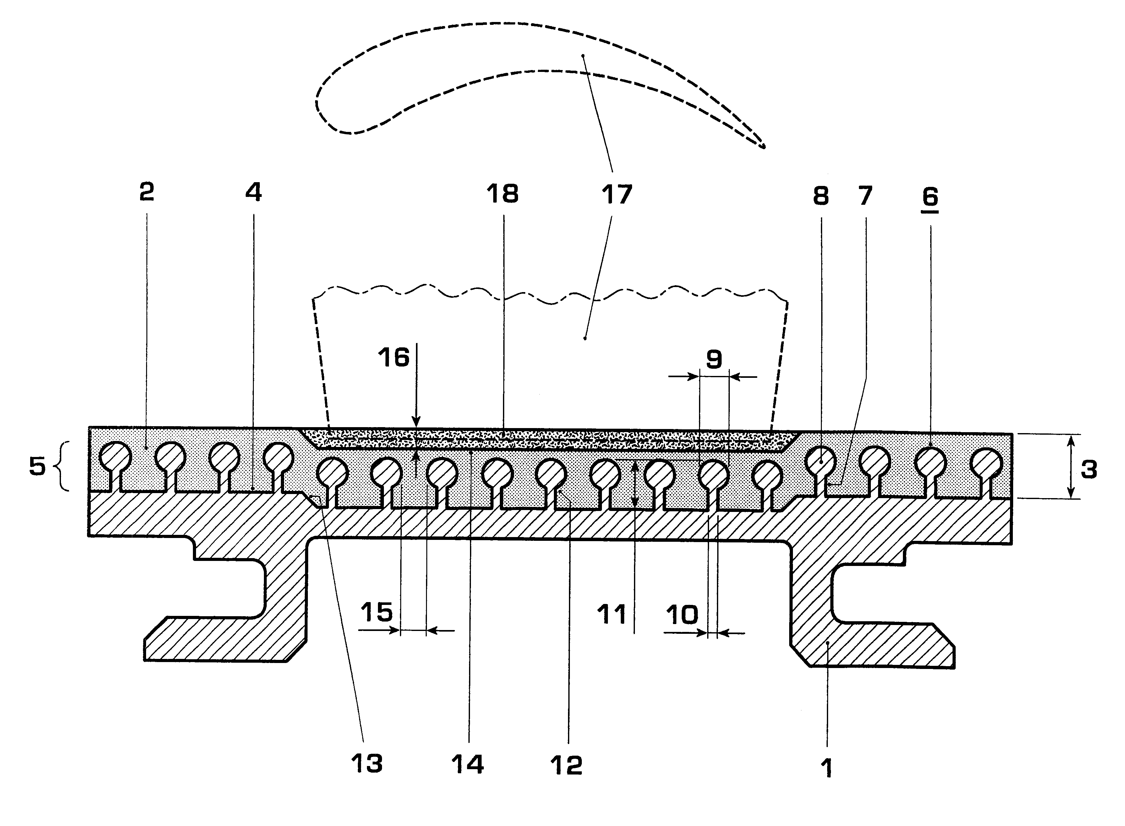
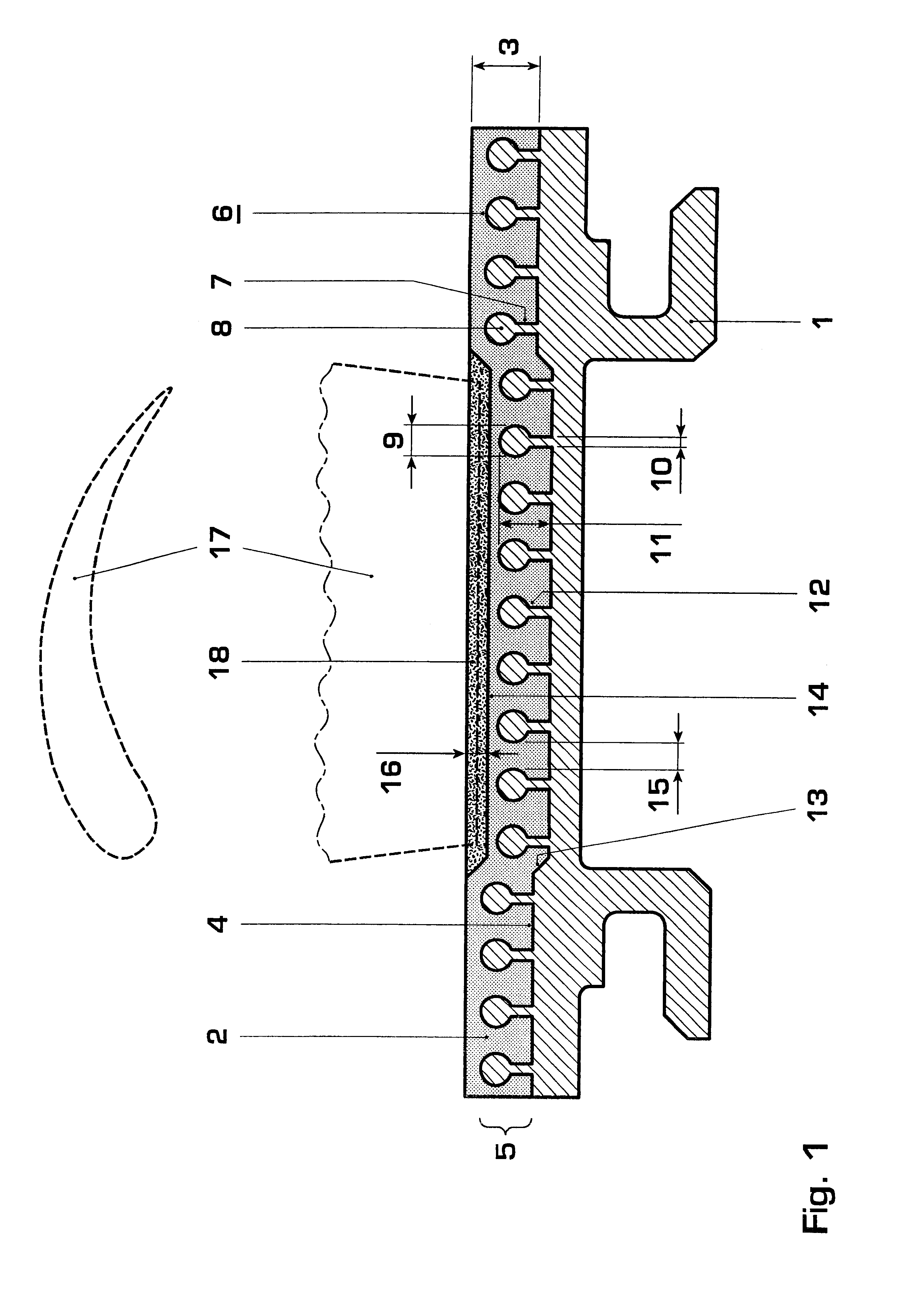
The invention is explained in more detail below with reference to exemplary embodiments and FIGS. 1 to 5.

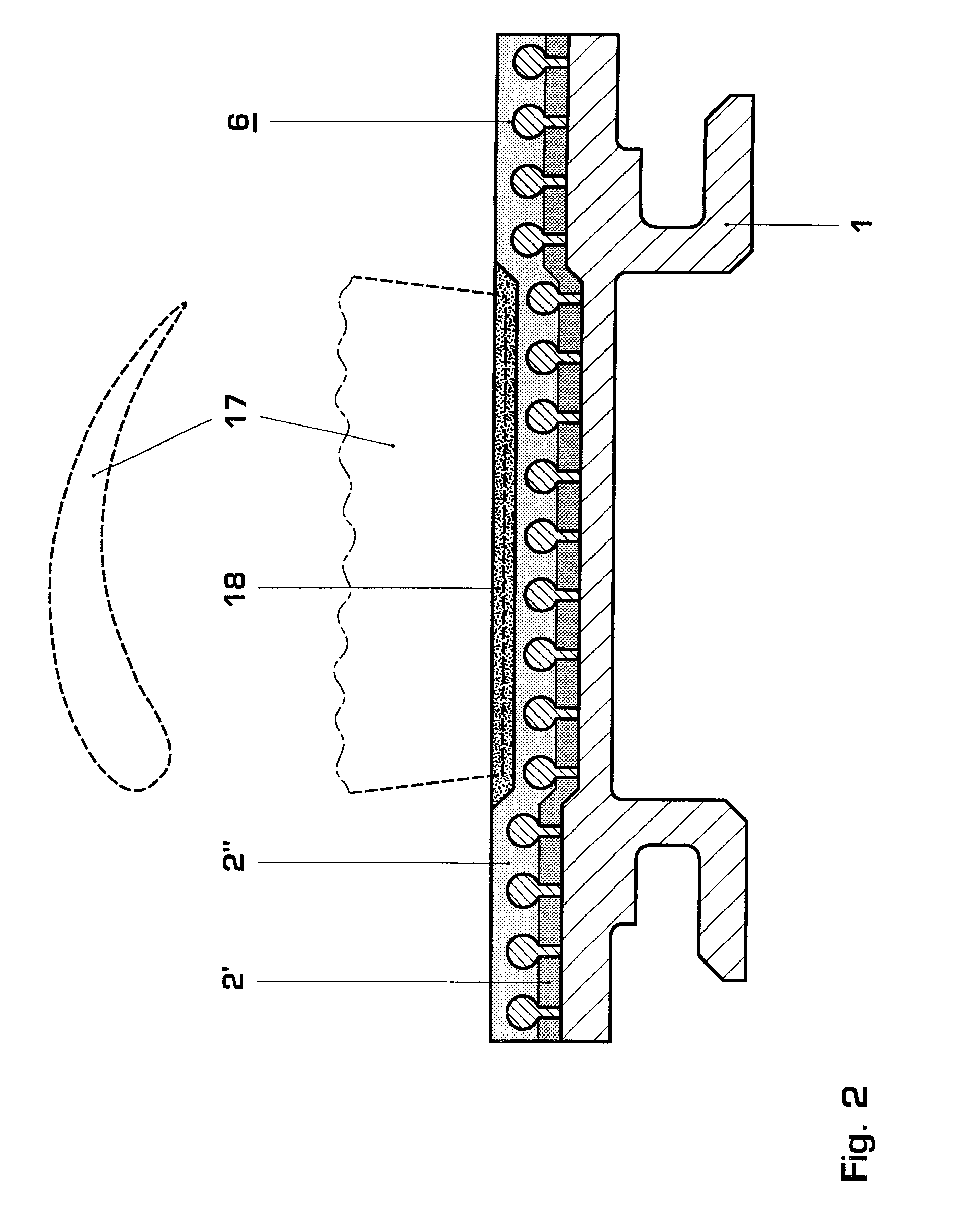
FIGS. 1 to 5 illustrate sections through four different variants of the gas turbine seal according to the invention. The figures in each case show a blade or vane tip seal.

FIG. 1 shows a blade or vane tip seal of a gas turbine, which comprises a metallic component 1, on which a durable or erosion-resistant ceramic layer 2, for example a thermal barrier coating comprising yttrium-stabilized zirconia of the following chemical composition: 2.5% of HfO.sub.2, 7-9% of Y.sub.2 O.sub.3, <3% of others, remainder ZrO, is sprayed by means of plasma spraying. Application by means of flame spraying is also possible. The layer 2 has a constant layer thickness 3, i.e. it follows the surface contour of the component 1, which as shown in FIG. 1 does not have a planar surface 4, but rather has a step 13. Therefore, at this location the layer 2 has a cavity 14.

To improve the bond strength of the l...


PUM

PropertyMeasurementUnit
depthaaaaaaaaaa
thicknessaaaaaaaaaa
thickaaaaaaaaaa

Abstract

The invention relates to a gas turbine seal, comprising a metallic component (1) with a durable or erosion-resistant ceramic coating (2) and an abradable ceramic layer (18) which is arranged thereon in locally delimited fashion, a bond layer (5) being arranged on the surface (4) of the metallic component (1), to which bond layer the durable or erosion-resistant ceramic coating (2) is applied as a covering layer. The invention is characterized in that the bond layer (5) comprises separate, adjacent spherical rivets (6) or mushroom-shaped rivets (6) which have a web (7) and a head (8). These rivets form individual metal islands with numerous undercuts (12), around which there is a continuous ceramic network. It is possible to produce very thick layers which have a good bond strength, the ceramic not being flaked away even in the event of introduction of radial / tangential forces, sickle-shaped contact or locally high overheating / frictional heat, and a good sealing action being achieved.

Description

The invention deals with the field of fluid dynamics. It relates to a gas turbine seal, comprising a metallic component with a durable or erosion-resistant ceramic coating and an abradable ceramic layer which is arranged thereon in locally delimited fashion. Coated components of this type are used, for example, for sealing and thermal insulation between rotating and stationary components in gas turbine installations.PRIOR ARTIt is known that, to increase the efficiency of thermal turbomachines, as far as possible there should be only small clearances between the housing and the rotating blade or vane tips in the compressor and in the turbine, in order to minimize or prevent leaks of air or combustion products between the two components, and thereby to keep losses at a minimum.One possible way of reducing such leaks is for the tolerances between the stationary and rotating components to be kept as tight as possible during manufacture and assembly of the components. However, this has ...

Claims


Application Information

Patent Timeline
Patent Type & Authority Patents(United States)
IPC IPC(8): F01D11/08F01D11/12
CPCF01D11/122F01D11/125Y02T50/67Y02T50/60
Inventor FRIED, REINHARD
Owner GENERAL ELECTRIC TECH GMBH
Why Eureka
Try Eureka