
Electrically conductive oil-based mud

a technology of oil-based mud and electric conductivity, which is applied in the field of oil-based muds or fluids, can solve the problems of poor image, unfavorable signal-to-noise ratio, and direct affecting the quality of the resolved imag

Inactive Publication Date: 2004-02-17
HALLIBURTON ENERGY SERVICES INC
View PDF26 Cites 46 Cited by
  • Summary
  • Abstract
  • Description
  • Claims
  • Application Information

AI Technical Summary

Benefits of technology

The present invention relates to oil-based muds or fluids used in drilling wellbores. More particularly, it relates to oil-based muds that are compatible with resistivity imaging techniques, such as electro-magnetic imaging (EMI). The invention aims to improve the quality of wellbore images by overcoming the challenges caused by the electrical conductivity of the oil mud and the dielectric properties of the formation. The invention proposes the use of additives that enhance the electrical logging results by bridging among themselves, linking the emulsified brine droplets, or a combination of these mechanisms. The invention also proposes the use of fluids that have low conductivity and no dielectric or capacitance properties, which are favorable for drilling or well service fluid applications.

Problems solved by technology

The electrical conductivity of a wellbore fluid directly affects the quality of the resolved image.
If the fluid is overly conductive, such as a concentrated salt brine, a poorer image may result due to an electrical short preventing good electrical penetration into the formation.
If the fluid behaves as a dielectric or a capacitor, the lack of a signal or an unfavorable signal-to-noise ratio may prevent satisfactory image resolution.
However, these fluids showed relatively high resistivities, making them unfavorable for most drilling or well service fluid applications.
Such fluids will not necessarily have the electrically conductive properties of a continuous aqueous phase.
The dielectric (electrically insulating) properties of the oil will undoubtedly have an effect in the field on the conductivity of the particles, causing such fluids to display conductivity having dielectric or capacitance properties, which in turn can result in the detected logging current having a poor signal-to-noise ratio.
Even where conductive properties seem favorable in lab tests, any source of multivalent cations in the actual wellbore, such as may be caused by lime or salt water flows in the field, can affect the conductive properties and result in a poor signal to noise ratio.
However, the fluid prepared according to the patent is actually not believed to be a true invert emulsion oil mud.
Because this fluid is not believed to be a true invert emulsion oil mud, it is not believed capable of preventing shale dispersion or inhibition in the manner of a traditional invert emulsion drilling fluid.
Further, mutual solvents are well known to have detrimental effects on polymeric components of rig equipment.
Although such additives may not show a significant improvement in fluid loss control when evaluated with filter paper, other porous media may show an improvement in filtration control upon the material's incorporation into the fluid.
However, the fluid requirements of resistance logging tools currently in use prevent an ECOM from being capable of creating a true oil phase barrier between the shale and the emulsified brine.
Such an exchange need not result in hydration, but may result in a modification of the ionic chemistry of the shale that may in some cases result in a `crumbling` of the shale.
While testing these pellets with an oil mud is traditional, a severe cuttings stability test was conducted, since these compressed pellets generally will disintegrate rapidly after exposure to various brines.
The reactive gumbo shale crumbled during the hot-rolling procedure; however, nearly all of it could be removed with relatively coarsely sized screens.

Method used


Image

  • Electrically conductive oil-based mud
  • Electrically conductive oil-based mud
  • Electrically conductive oil-based mud

Examples


Embodiment Construction

Test samples of example ECOM formulations were prepared for laboratory testing as follows:

1. To a mixing cup add the PETROFREE.RTM.LV, GELTONE.RTM.II, DURATONE.RTM.HT, lime, DF-01 (or DF-03), and EZ MUL.RTM.NTE. Shear on a multimixer for 10 minutes.

2. Add the calcium chloride brine and shear for 10 minutes.

3. Treat with RS1100.TM., 1 lb / bbl of DEEP-TREAT.TM., and shear for 5 minutes. The fluid's viscosity will increase during this process.

4. Treat with Disponil SML.TM. and allow to shear for 5-10 minutes. The fluid may still appear quite viscous at this point in the procedure.

5. Add weighting material and other solids to the fluid. Shear 20-30 minutes, or until viscosity reduction is noticed.

6. Hot-roll the fluid overnight or go directly to higher temperature aging.

7. Confirm electrical conductivity using a dip-probe conductivity meter capable of measuring values as small as 1 .mu.s / cm.

Laboratory Testing Indicated the Following General Results and Conclusions:

The preferred base flui...


PUM

PropertyMeasurementUnit
volume percentaaaaaaaaaa
frequencyaaaaaaaaaa

Abstract

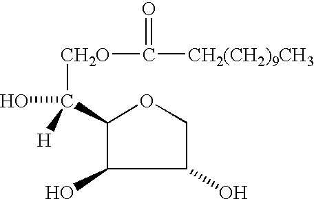
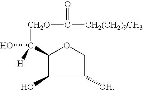
An electrically conductive oil mud meeting the fluid requirements for resistive logging tools and a method for preparing such mud is disclosed. The fluid has been optimized to deliver performance in a manner as similar to that of a traditional invert emulsion drilling fluid as is practical while still maintaining the required electrical conductivity for resistivity-based logging tools. This electrically conductive oil-based mud comprises a polar synthetic ester base and complimentary ester surfactants, one being more oil soluble, the other being more water soluble. The surfactants interact synergistically to provide dense packing of micelles at the palisade layer. This fluid is oil-wetting to solids, and in general behaves like a traditional oil mud.

Description

1. Field of the InventionThe present invention relates to oil-based muds or fluids for use in drilling wellbores in subterranean formations. More particularly, the invention relates to oil-based muds suitable or compatible for use with resistivity imaging of the wellbore or the formation.2. Description of Relevant ArtIn the oil and gas industry, there are generally three primary or commonly used techniques for imaging of wellbores. These three techniques are: acoustic imaging, azimuthal density neutron imaging, and resistivity imaging. Of the three, resistivity imaging is often preferred for its relative simplicity of operation, rapid acquisition of real-time data, and highly accurate images of geological features.Resistivity imaging techniques are based on measurements of the electrical resistance of the formation exposed to the wellbore. Tools based on this technique, such as Halliburton's Electro-Micro-Imager.TM. (EMI), available from Halliburton Energy Services, Inc. in Houston,...

Claims


Application Information

Patent Timeline
Patent Type & Authority Patents(United States)
IPC IPC(8): C09K8/32C09K8/02E21B47/00G01V3/18G01V3/20
CPCC09K8/32E21B47/00G01V3/20Y02A90/30
Inventor THAEMLITZ, CARL JOSEPH
Owner HALLIBURTON ENERGY SERVICES INC
Learn More