

Methods and apparatus for disposing of deleterious materials from a well
a technology for removing deleterious materials and wells, which is applied in the direction of passenger handling apparatus, borehole/well accessories, vessel construction, etc., can solve the problems of high cost, many installation hours, and complicated environmental problems, and achieve the effect of reducing the number of installation hours and high cos
- Summary
- Abstract
- Description
- Claims
- Application Information
AI Technical Summary
Benefits of technology
Problems solved by technology
Method used
Image

Examples
Embodiment Construction
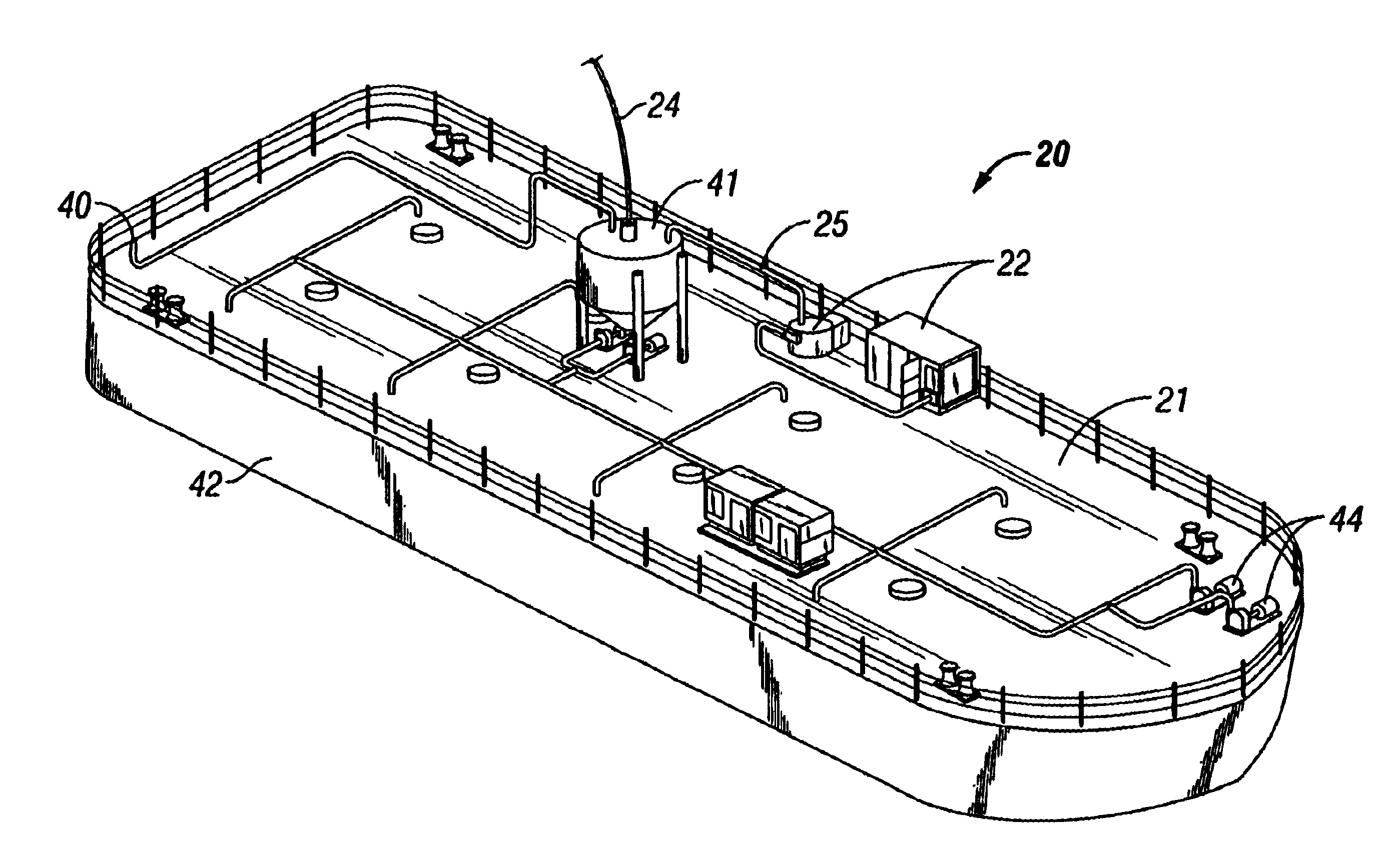
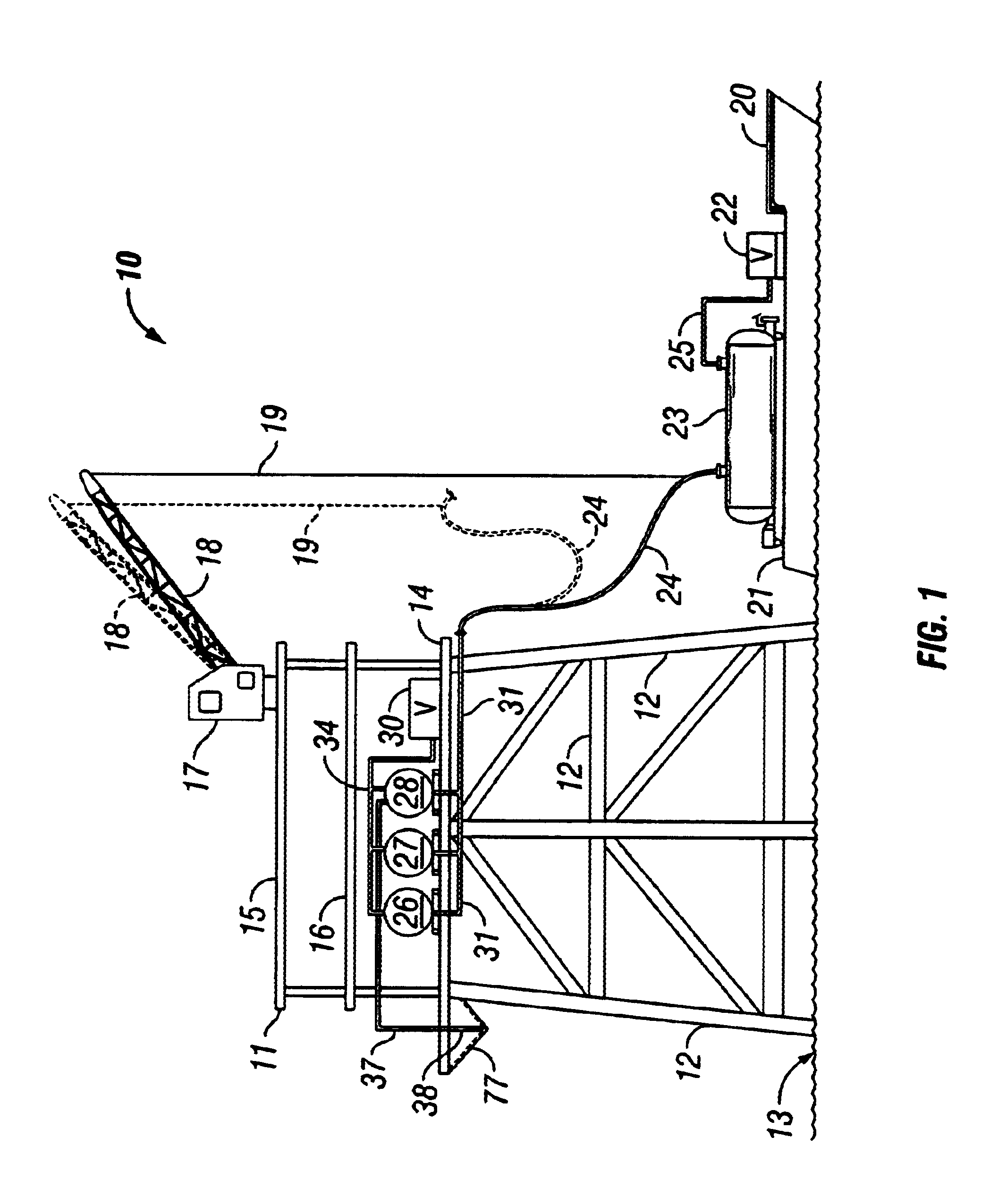
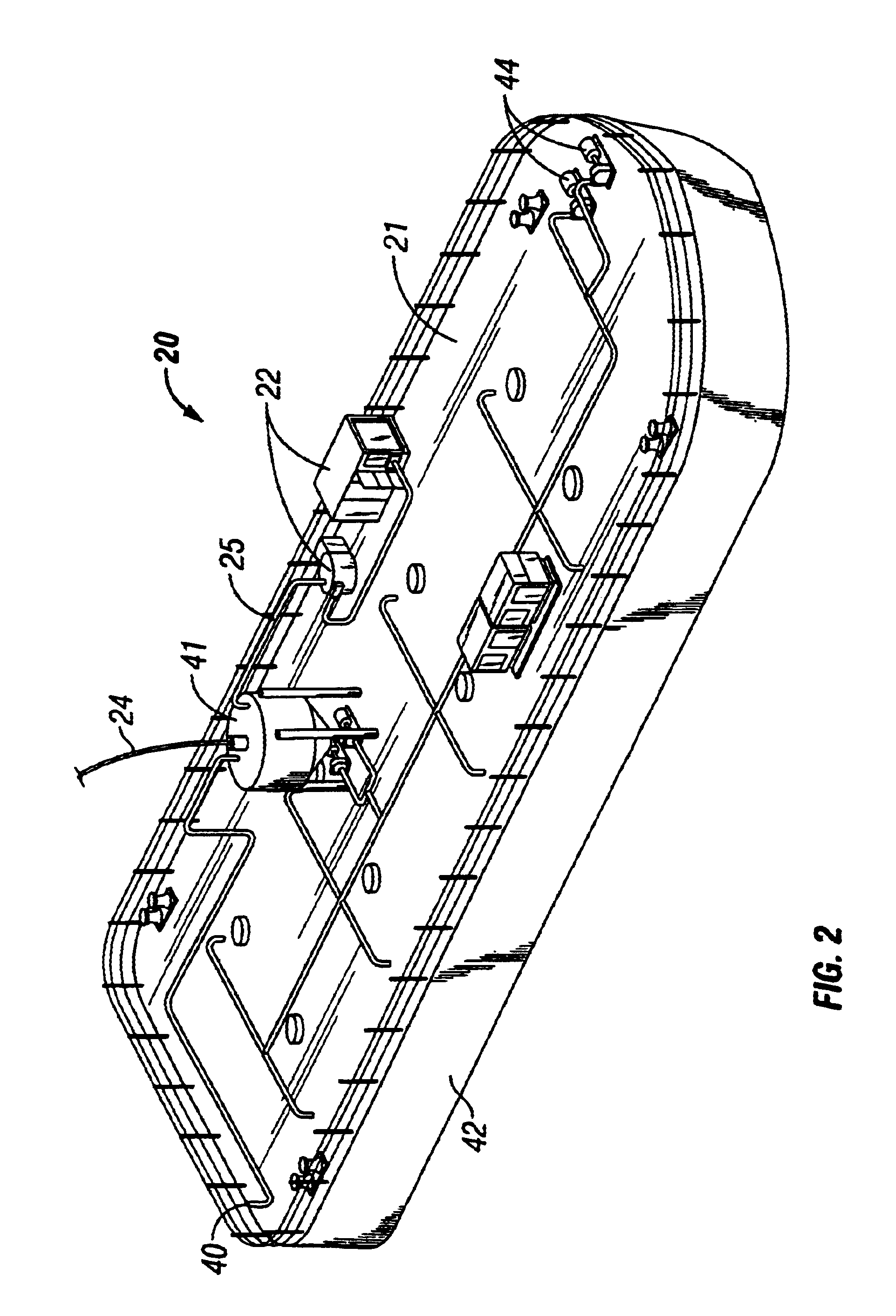
The preferred embodiment provides an improved method and apparatus for processing well deleterious material on a floating vessel during transportation from an offshore well to a disposal site. Deleterious material can include, but is not limited to, drilling cuttings, drilling mud, and / or other waste products, or any combination thereof. It should be appreciated that processing can include, but is not limited to, slurrification, agitation, separation, and / or chemical treatment, or any combination thereof. The vessel contains equipment for the processing of the deleterious material. Such equipment includes, but is not limited to, slurrification equipment, storage tanks, and / or agitation equipment, as well as transfer equipment such as flow lines and vacuum or pump means. The deleterious material is transferred from the well to the storage tanks on the vessel. The vessel then transports the material to a disposal site, such as an injection well rig. During transportation, the deleteri...
PUM
 Abstract
Description
Claims
Application Information