Cement mixing system for oil well cementing

a cement mixing and oil well technology, applied in the field of high efficiency, high energy slurry mixers, can solve the problems of high equipment and labor intensity, large equipment investment, and high cost of space and weight capacity, and batch mixers use valuable space and add to rig weigh

Inactive Publication Date: 2004-06-15
SERVA CORP
View PDF19 Cites 38 Cited by
  • Summary
  • Abstract
  • Description
  • Claims
  • Application Information

AI Technical Summary

Benefits of technology

The prior U.S. Pat. No. 5,571,281 mixer provides "baffled" annular space through which recirculated flow passes. This design is unnecessarily restrictive to the recirculation flow and has a low coefficient of discharge. The flow path of the present invention for annular recirculated flow is more streamlined and thus has a higher coefficient of discharge. With a higher coefficient of discharge, this means that pressure head is converted to velocity more efficiently and therefore provides the same mixing energy with less input horsepower.
One object of the present invention is to improve the mixing capabilities as compared to prior art mixers. The present invention will provide more effective and efficient mixing over a wide range of conditions, including both batch mixing and continuous mixing modes.
A third object of the present invention is to provide both a centrally located recirculation jet and a plurality of equally spaced annular recirculation jets. Bulk cement enters the mixer and encounters high energy jets from the center and from annular jets. These jets have trajectory angles which intercept the dry bulk, breaking it apart and effectively wetting the incoming dry bulk.
A fourth object of the present invention is to provide a plurality of annular and adjustable water jets located at alternate positions from the annular recirculation jets. These jets, in combination with the recirculation annular jets, provide improved mixing and more effective wetting of the bulk cement.
A fifth object of the present invention is to provide a mixing system that provides more predictable slurry properties due to improved and effective mixing.
A sixth object of the present invention is to provide a mixer which provides high mixing energy while consuming less energy.

Problems solved by technology

Batch mixing is one form of system to obtain a satisfactory slurry, but batch mixing requires an initial outlay of a large amount of equipment, people, and space.
In offshore operations, space and weight capacity are expensive.
Batch mixers use valuable space and add to rig weight.
Typically, large tanks with rotary paddle type mixers, although being able to adequately perform the mixing operations, have not been efficient in term of space, numbers of people required or equipment costs where large volumes of mixing must be done at the well site.
For example, jet-type mixers and vortex mixers such as those disclosed in U.S. Pat. Nos. 3,201,093 and 3,741,533 have been used with considerable success but have not necessarily been successful in continuously mixing cement slurries.
With the more enhanced slurry designs of today, the jet mixer cannot adequately mix these slurries.
Since that time, cement slurry design has evolved into the use of more complex slurries that earlier continuous mixing systems are unable to mix satisfactorily.
It seems as though the industry is constantly testing the ability of mixers by developing even more difficult to mix slurries.
Although prior inventions have taught use of centrally located recirculation jets, or alternately, annularly located recirculation jets, none of the prior art teaches or suggests the desirability of providing both centrally located and annularly located recirculation jets.
The short coming of the U.S. Pat. No. 5,571,281 mixer was when mixing slurries that had a low water requirement, i.e. small number of gallons of water per sack of cement, or when the mixer was used in a batch mode, there is insufficient energy to effectively wet all the incoming dry bulk cement.
Also, the U.S. Pat. No. 5,046,855 mixer also suffered from discrete mix water jets.
Coverage was good when all jets were open, but when only the first set of jets was operational due to low mix rate or low water requirement or both, coverage was poor and mixing quality suffered.
This design is unnecessarily restrictive to the recirculation flow and has a low coefficient of discharge.
Present technology performance during this mode of operation is significantly degraded.

Method used


Image

  • Cement mixing system for oil well cementing
  • Cement mixing system for oil well cementing
  • Cement mixing system for oil well cementing

Examples


Embodiment Construction

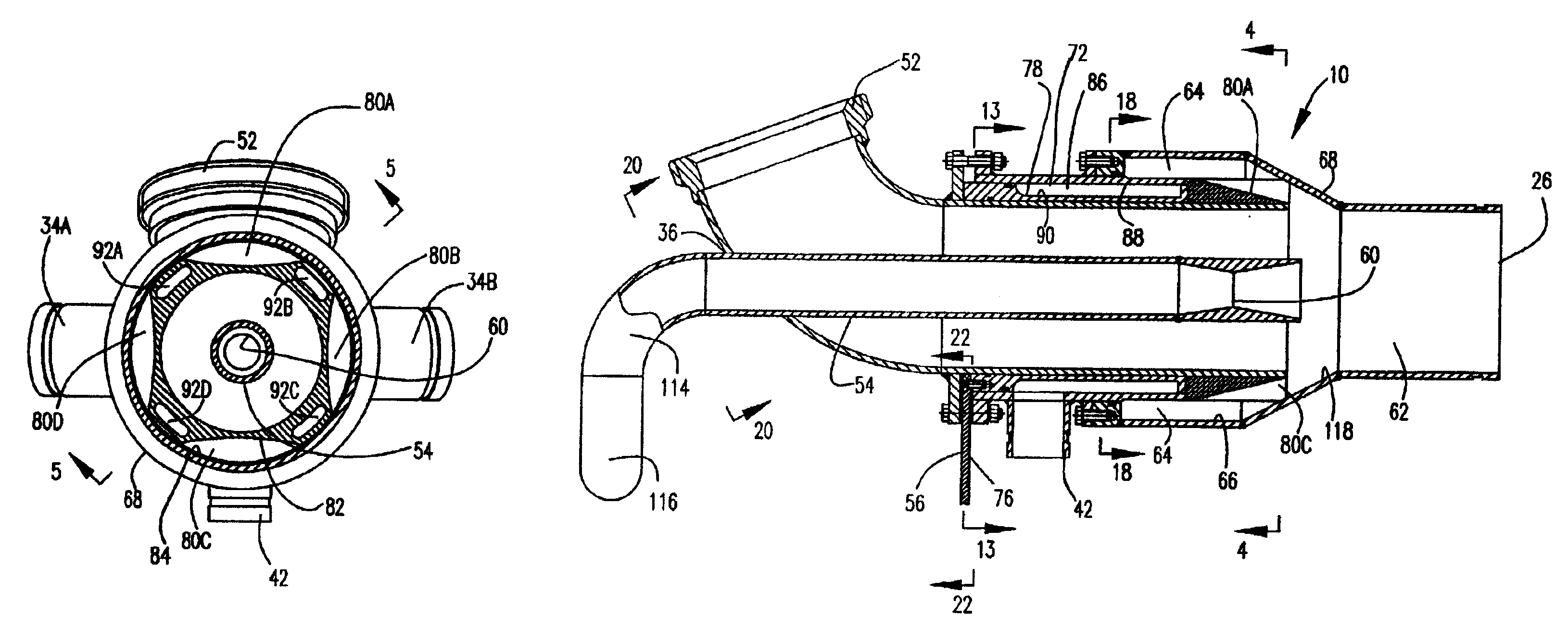
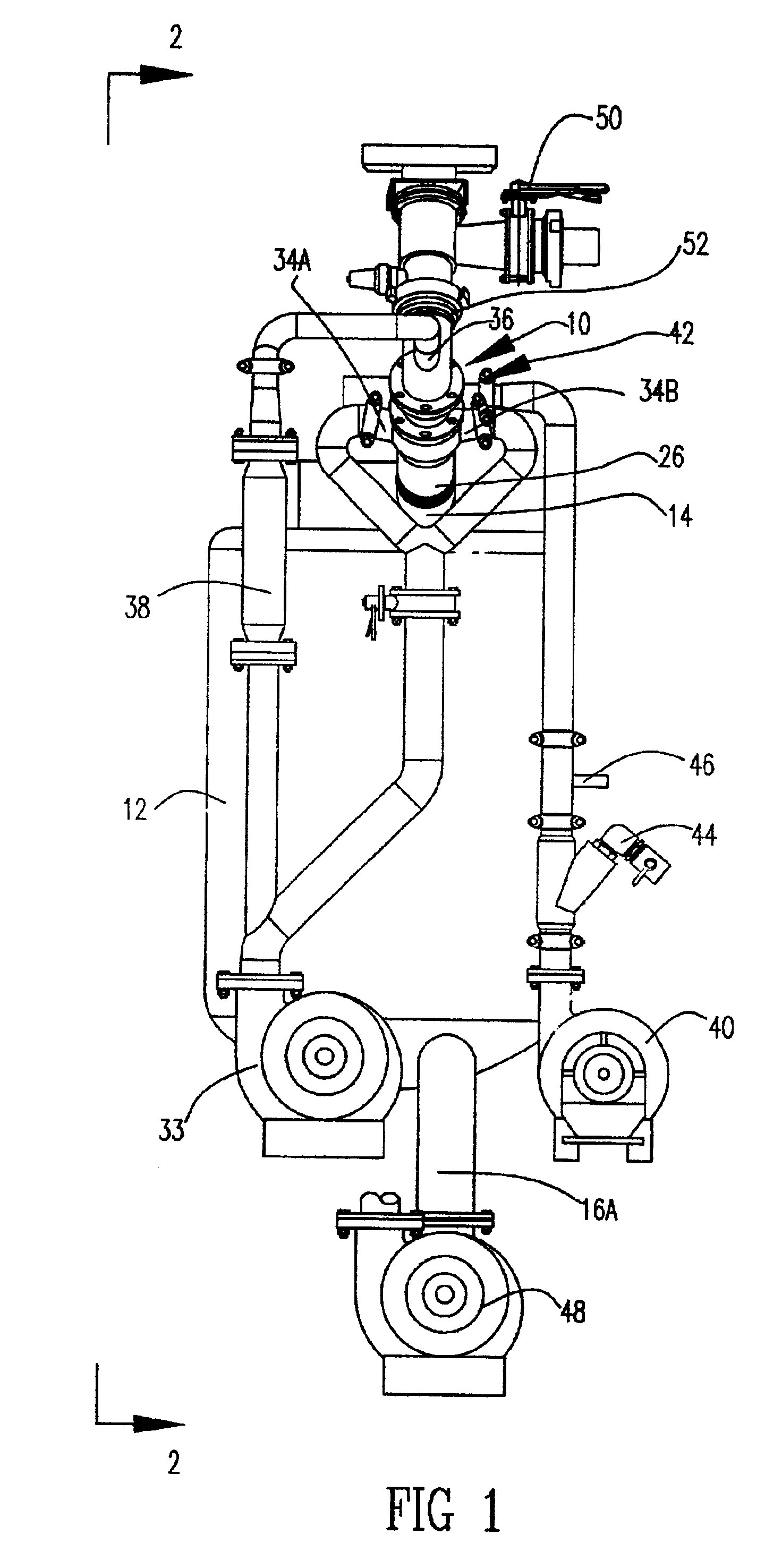
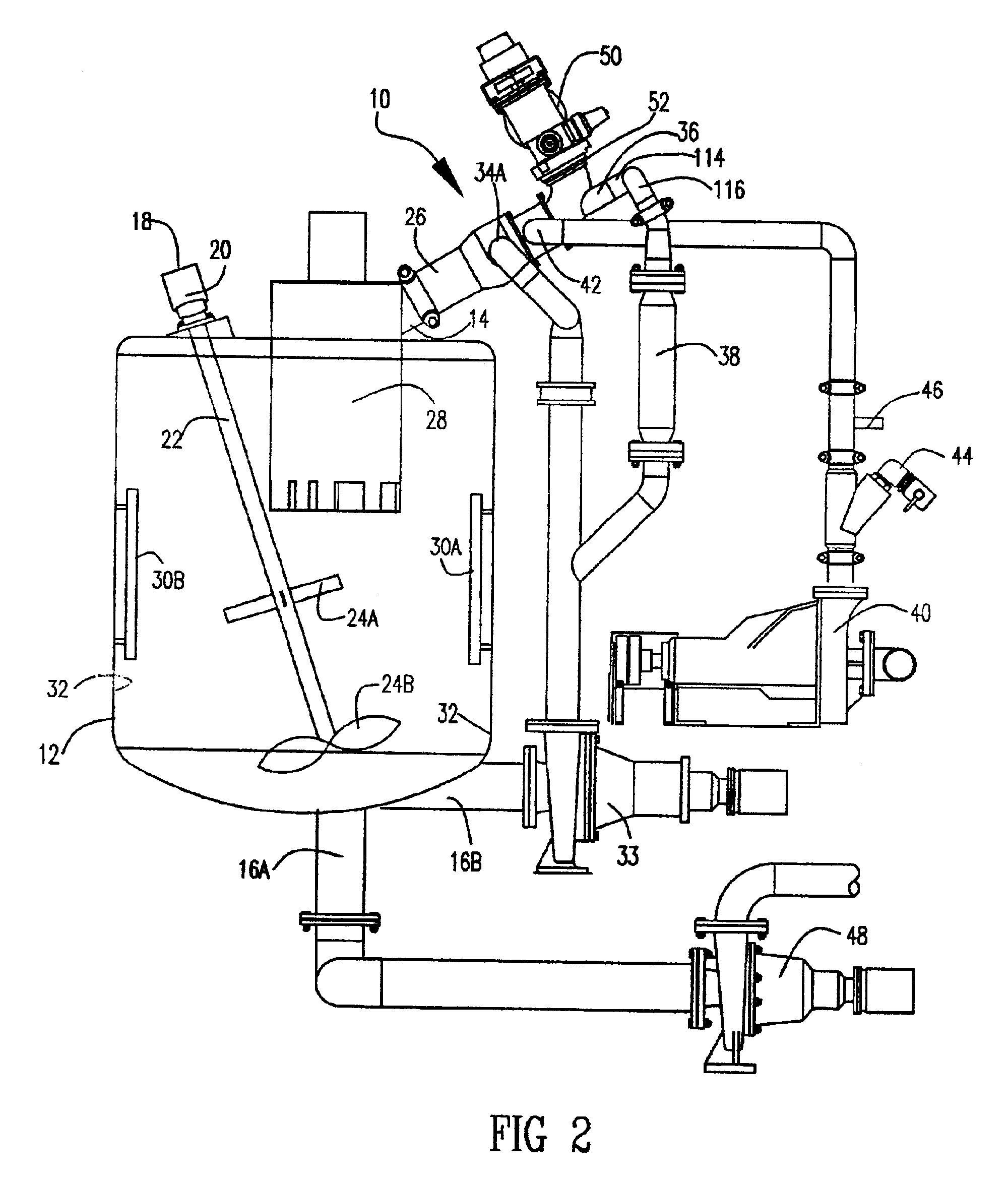
Referring now to the drawings, the present invention is a cement mixing system and mixer 10 for mixing cement that will be used in cementing oil wells. The overall typical system within which the mixer 10 is likely to be used is illustrated in FIGS. 1 and 2. The mixer discharges into a mixing tank 12, which is similar to other mixing tanks found in literature and in practice. The tank 12 is designed for continuous mixing with a steady throughput rate with a tank inlet 14 for incoming fluids and one or more tank outlets 16A and 16B for discharging mixed fluids. The tank 12 is equipped with an agitator 18 for further mixing and homogenizing the contents of the tank 12. The agitator 18 is comprised of a motor 20, shaft 22, and various agitator blades 24A, 24B, etc.

An outlet 26 of the mixer 10 is attached to the tank inlet 14, and the tank inlet 14 is attached to a passive separator device 28 which centrifugally separates air from the liquid mixture. Fixed plates 30A, 30B, etc are attac...


PUM

PropertyMeasurementUnit
pressureaaaaaaaaaa
sizeaaaaaaaaaa
outer diameteraaaaaaaaaa

Abstract

A powder mixing system and mixer for mixing cement used in cementing oil wells or other similar dry powder mixtures. The mixer is provided with a central recirculation jet and with annularly located alternating recirculation and mix water jets that discharge into the mixing chamber of the mixer in an overlapping fashion to effectively wet dry cement introduced into the mixing chamber. The mix water jets are formed from a set of slots provided both in a rotatable element and from another set of slots provided in a stationary portion so that when the rotatable element rotates, the size of mix water jets is adjusted. Two inlet elbows attach to the inlet of the central recirculation jet to cause the flow from the jet to rotate in a diverging pattern.

Description

1. Field of the InventionThe present invention relates to a high efficiency, high energy slurry mixer used primarily to mix oil field cement in a recirculating system for cementing the casing in oil and gas wells. Specifically, the present invention employs continuous recirculation via a central recirculation line and via annular recirculation jets that are spaced alternately with annular adjustable mix water jets.2. Description of the Related ArtUtilization of cement within oil wells, particularly in the cementing of casing therein, has been under development since the early 1900's. Two of the purposes of placing cement into the annular space between the casing and the formation are to support the casing within the well, and to seal off undesirable formation fluids.Casing is typically secured in the well bore by the cement which is mixed at the surface, then pumped down the open center of the casing string and thence back up the annular space which exists between the outer diameter...

Claims


Application Information

Patent Timeline
Patent Type & Authority Patents(United States)
IPC IPC(8): B01F5/02B01F5/04B28C5/00B28C5/06B01F3/12B01F5/00B01F5/10
CPCB01F5/02B01F5/0275B01F5/0453B28C5/06B01F5/10B01F2003/1257B01F23/565B01F25/27B01F25/20B01F25/3132B01F25/50
Inventor ALLEN, THOMAS E.
Owner SERVA CORP
Why Eureka
Try Eureka