
Laser assisted track width definition and radial control with magnetic recording

a technology of magnetic recording and track width, applied in the direction of maintaining head carrier alignment, light beam reproducing, instruments, etc., can solve the problems of high servo error rejection, inability to write radial and circumferential position sensing patterns (servo writing), and the magnetic storage drive technology is subject to the "super paramagnetic limit", so as to improve the signal-to-noise ratio (snr) and improve the storage capacity of the data disk drive. , the effect o

Inactive Publication Date: 2004-08-10
SEAGATE TECH LLC
View PDF33 Cites 26 Cited by
  • Summary
  • Abstract
  • Description
  • Claims
  • Application Information

AI Technical Summary

Benefits of technology

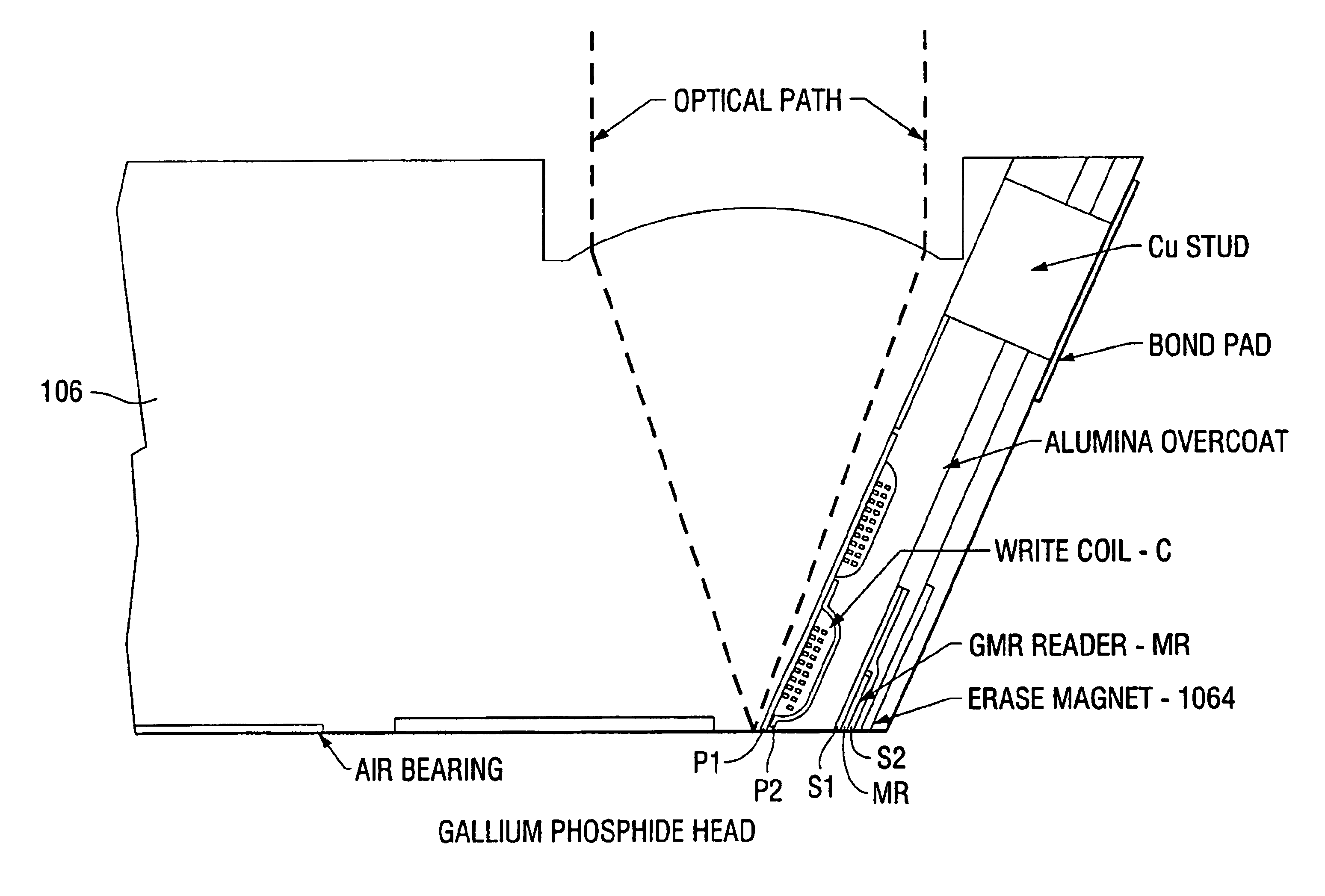
The present invention provides for the enhancement of the storage capacity of a data disk drive while reducing optical path optics, electronics and / or the mass and complexity of associated read / write heads. The system utilizes light transmitted by optical elements to servo track a data disk and to heat the data disk during writing and reading of data, and inductive and magnetic elements for actual writing and reading. In doing so, the present invention provides an improved signal-to-noise-ratio (SNR) for a signal that is representative of data recorded as regions of magnetic domain marks on the data disk as well as improved storage capacity of the disk drive.
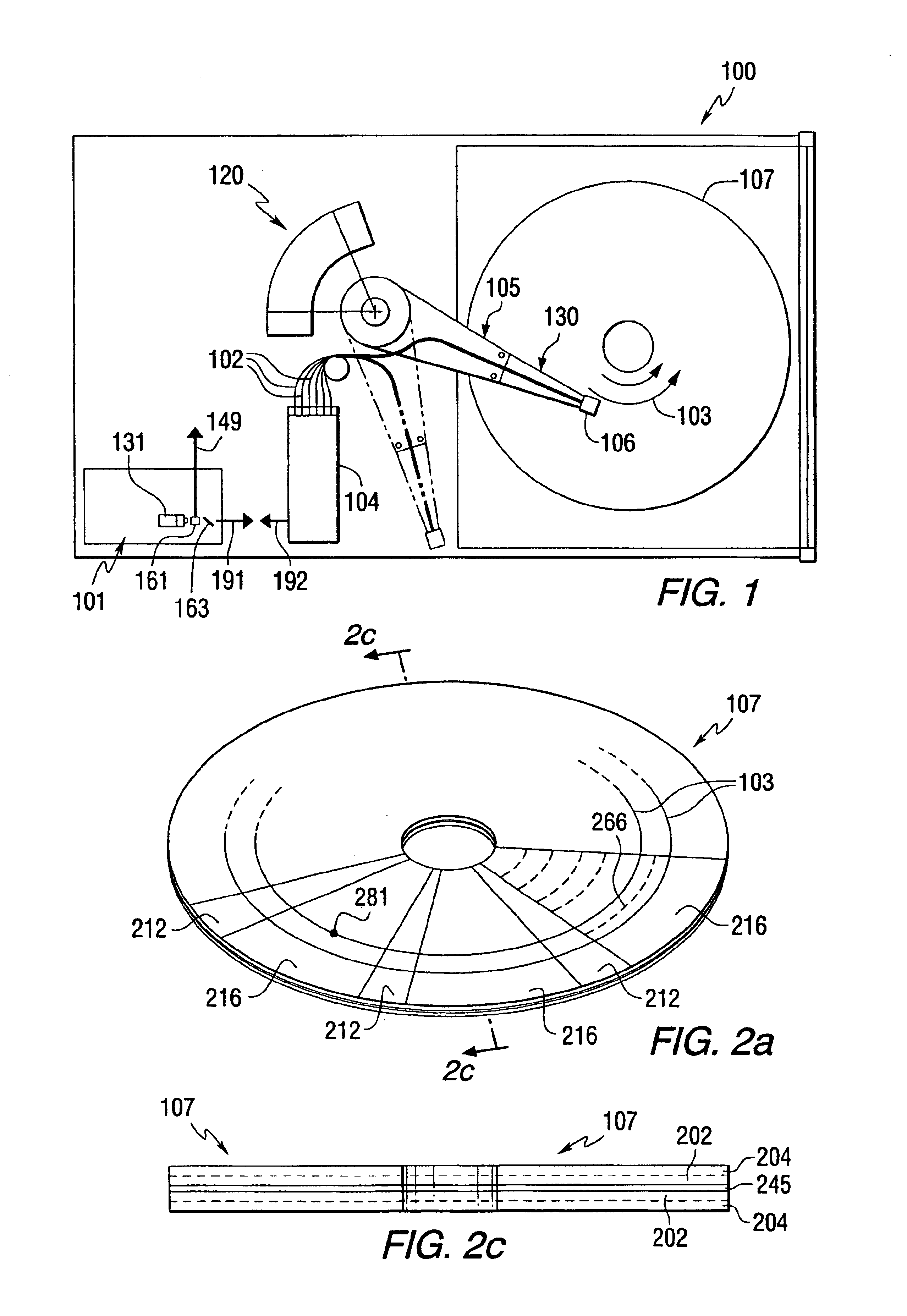
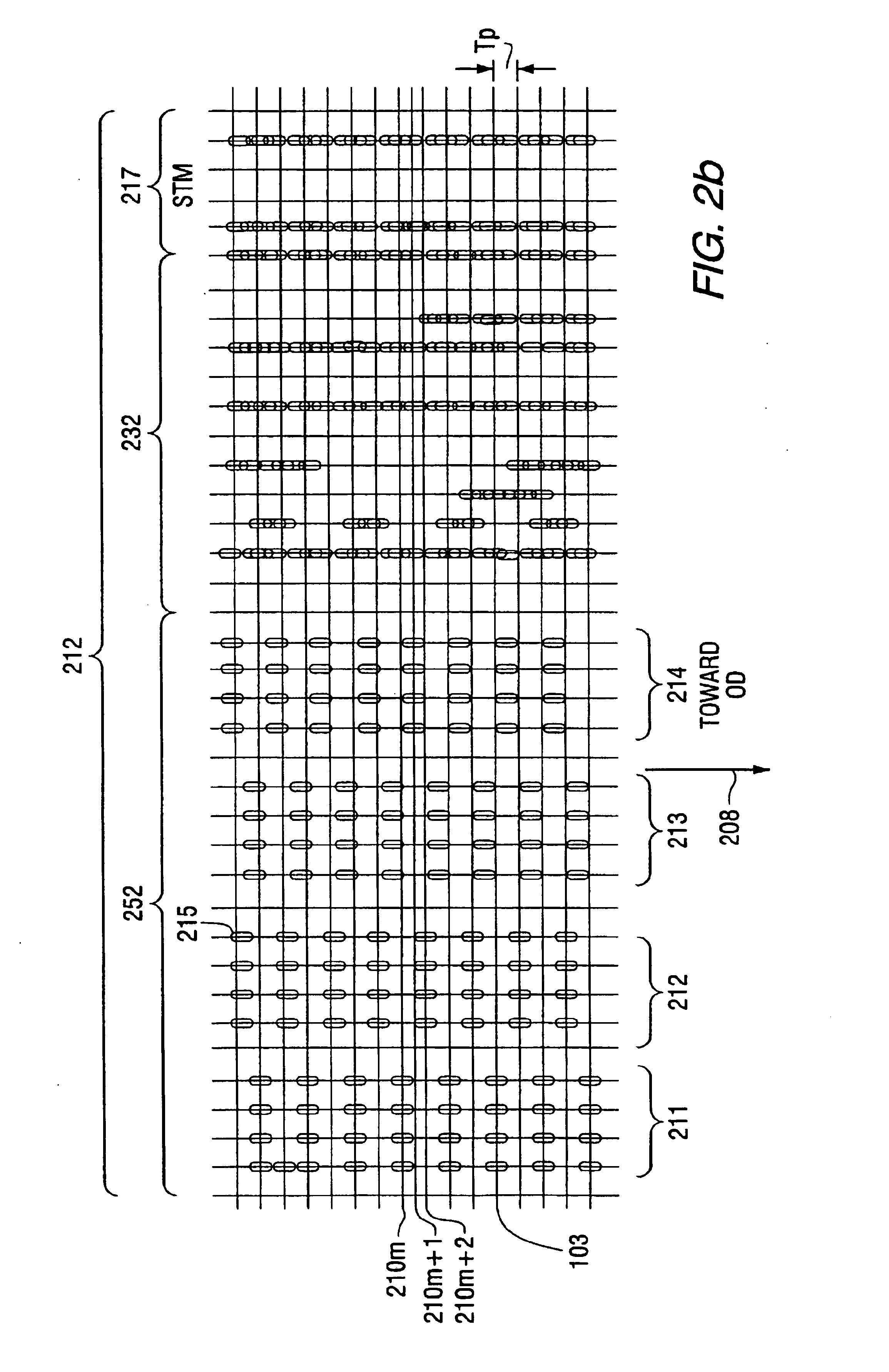
The data storage disk may include depressions and / or raised features, which may be filled and / or polished with various materials. In this way, a smooth surface is provided for the read / write head that is aerodynamically maintained in a flying condition very close to the data disk surface. By providing a smooth surface, accumulation of contaminants may be reduced or eliminated. The filler material may be made to be reflective such that an optical signal reflected from the depressions and / or raised features can be provided with a larger amplitude. The reflection of the light from the material used for filling the depression and / or raised feature may be used for sector identification and track following. Additionally, the depressions and / or raised features may be made to present a reflective area that is proportional to the radius of the data disk at which they are disposed. Consequently, the frequency content and / or amplitude variations of the reflected optical signal may be minimized over a radius of the data disk.

Problems solved by technology

Magnetic storage drive technology is subject to the "super paramagnetic limit", which simply states that when longitudinally oriented (in plane) magnetic domains are written in granular thin film metallic media, these domains will tend to demagnetize each other at some high flux reversal density and at high temperature.
1) For tracking, a very high servo error rejection needs to be implemented, which requires a coarse and fine tracking actuator, for example, a crossover frequency of greater than 2 Khz is required for a track pitch of 1 .mu.m.
2) The photolithographic tolerances for making a read / write head is limited to about 10% of the thickness of the head permalloy poles. If the poles are about 4 .mu.m thick, the head tolerances are about 0.4 .mu.m.
3) A typical prior art head causes side-erasure of data tracks of about 0.3 .mu.m. This side erasure is desired for proper operation during the record / playback process so as to eliminate old information. Because, side-erasure scales with the head gap width, the gap width will be a function of a desired magnetic domain density.
4) The writing of the radial and circumferential position sensing patterns (servo writing) is not very accurate because of disk flutter and spindle bearing non-repeatable runout. One can typically expect a servo writing accuracy of about 0.2 .mu.m with 0.8 mm thick 3.5 inch disks spinning on a ball bearing spindle.

Method used


Image

  • Laser assisted track width definition and radial control with magnetic recording
  • Laser assisted track width definition and radial control with magnetic recording
  • Laser assisted track width definition and radial control with magnetic recording

Examples


Embodiment Construction

The present invention provides for the enhancement of the storage capacity of a data disk drive while reducing optical path optics, electronics and / or the mass and complexity of associated read / write heads. The system utilizes light transmitted by optical elements to servo track a data disk and to heat the data disk during writing and reading of data, and inductive and magnetic elements for actual writing and reading.

The data storage disk may include depressions and / or raised features, which may be filled and / or polished with various materials. In this way, a smooth surface is provided for the read / write head that is aerodynamically maintained in a flying condition very close to the data disk surface. By providing a smooth surface, accumulation of contaminants may be reduced or eliminated. The filler material may be made to be reflective such that an optical signal reflected from the depressions and / or raised features can be provided with a larger amplitude. The reflection of the li...


PUM


Abstract

The present invention provides for the enhancement of the storage capacity of a data disk drive while reducing optical path optics, electronics and / or the mass and complexity of associated read / write heads. The system utilizes light transmitted by optical elements to servo track a data disk and to heat the data disk during reading and writing of data, and magnetic elements for actual reading and writing.

Description

The present invention relates to data storage and retrieval systems that utilize optical and magnetic elements.In prior art magneto-optical (MO) disk drives, data is read as a clockwise or counter-clockwise polarization rotation imposed on a polarized laser light by the up or down orientations of magnetic domains within an area of stored data. The minimum area that the data can comprise is a function of the size of an optical spot formed by the polarized light. The information embedded in the polarization rotation requires an optical readout means. The optical readout means in the prior art includes a plurality of bulky and complex optical elements, some of which are located on a magneto-optical head. The optical elements can degrade the signal to noise ratio (SNR) of the information signal obtained from the polarization rotation.Magnetic based disk drives are also well known in the art. In magnetic drives, magneto-resistive elements on magnetic heads are typically used. Recent adva...

Claims


Application Information

Patent Timeline
IPC IPC(8): G11B11/105G11B11/00G11B5/00G11B23/00G11B5/84G11B5/596G11B21/10G11B5/012G11B5/82G11B5/48G11B5/49G11B13/00G11B13/04G11B5/39G11B7/085G11B7/30
CPCB82Y10/00B82Y25/00G11B5/00G11B5/012G11B5/4886G11B5/4969G11B5/596G11B5/59677G11B5/82G11B5/84G11B11/1055G11B11/10554G11B11/10578G11B11/10582G11B11/10584G11B21/106G11B23/0021G11B23/0057G11B7/08564G11B11/10536G11B11/10563G11B11/10576G11B11/1058G11B13/045G11B2005/0002G11B2005/0005G11B2005/0021G11B2005/3996
Inventor BELSER, KARL A.MCDANIEL, TERRYGAGE, EDWARD C.DURNIN, JAMESSWANSON, LORI G.HUTCHINSON, CHRISTINA L.
Owner SEAGATE TECH LLC
Learn More