Eureka AIR delivers breakthrough ideas for toughest innovation challenges, trusted by R&D personnel around the world.

Ultrasonic transducer and ultrasonic flowmeter using same

a technology of ultrasonic flowmeter and transducer, which is applied in the direction of liquid/fluent solid measurement, mechanical vibration separation, instruments, etc., can solve the problems of inferior durability, difficult to determine the time of flight, and heterogeneous medium

Inactive Publication Date: 2004-08-17
PANASONIC CORP
View PDF5 Cites 18 Cited by
  • Summary
  • Abstract
  • Description
  • Claims
  • Application Information

AI Technical Summary

Benefits of technology

Such objects and advantages of the present invention will become more apparent from the following description of embodiments given by reference to the accompanying drawings.
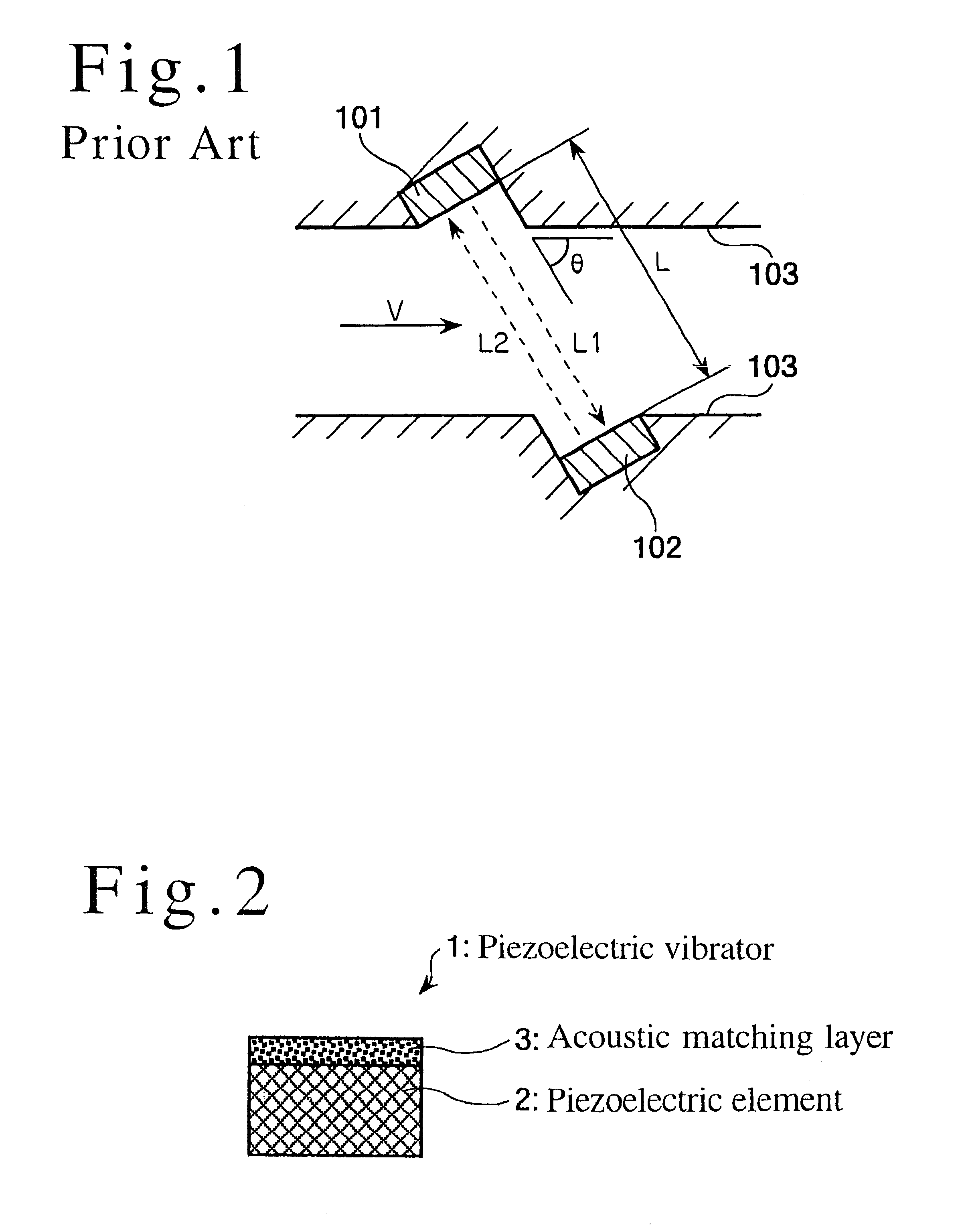
FIG. 1 is a cross sectional view showing the measurement principle of a conventional ultrasonic flowmeter;
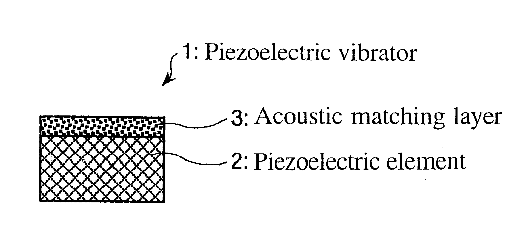
FIG. 2 is a cross sectional view of an ultrasonic transducer shown as a first embodiment of the present invention;
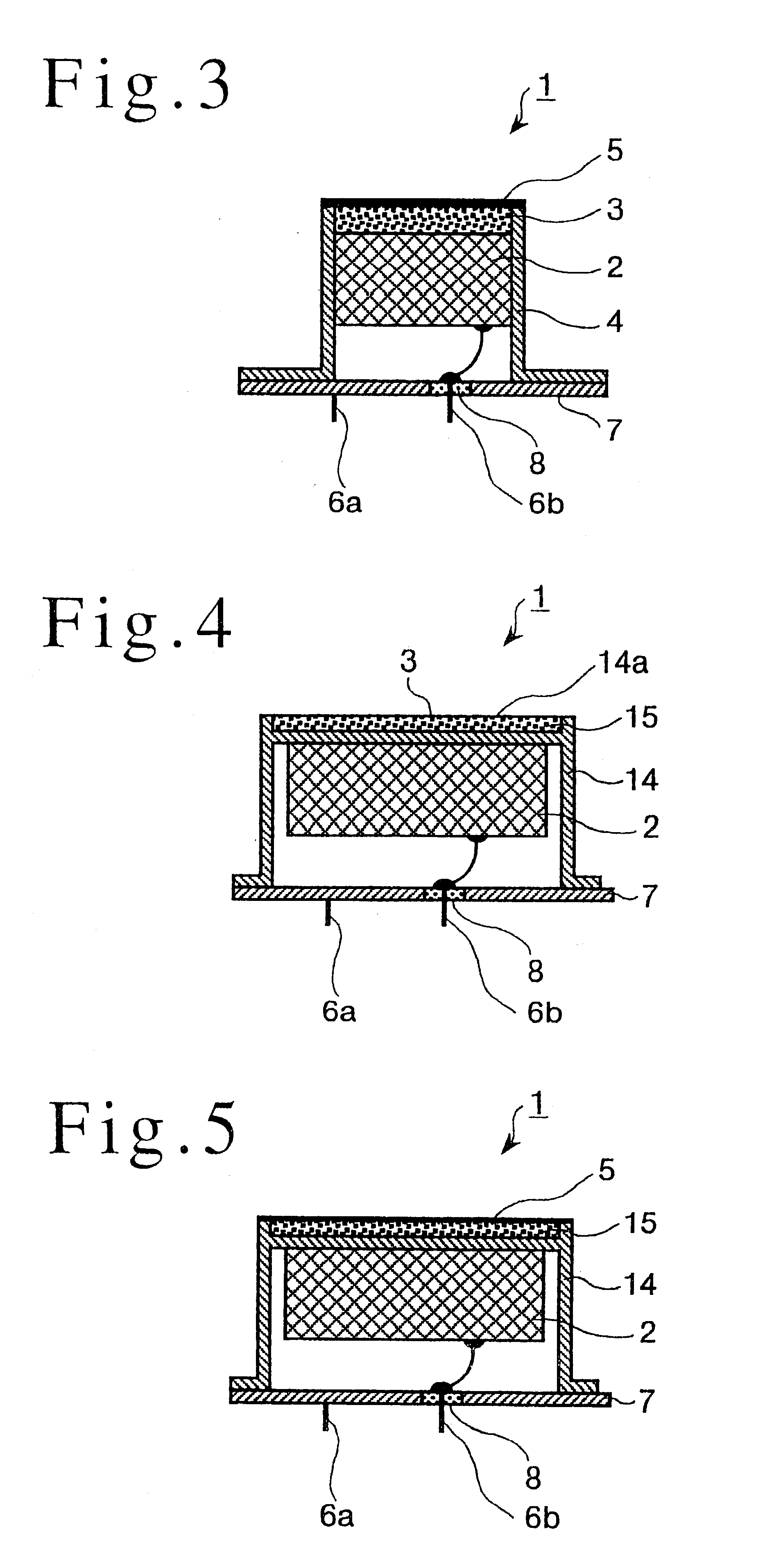
FIG. 3 is a cross sectional view of an ultrasonic transducer shown as a second embodiment of the present invention;
FIG. 4 is a cross sectional view of an ultrasonic transducer shown as a third embodiment of the present invention;
FIG. 5 is a cross sectional view of an ultrasonic transducer shown as a fourth embodiment of the present invention
FIG. 6 is a flow chart illustrating a first example of a manufacturing method of the ultrasonic transducer of the present invention;
FIG. 7 is a flow chart illustrating a second example of a manufacturing method of the ultrasonic transducer of the present invention;
FIG. 8 is a flow chart illustrating a third example of a manufacturing method of the ultrasonic transducer of the present invention;
FIG. 9 is a flow chart illustrating a fourth example of a manufacturing method of the ultrasonic transducer of the present invention; and
FIG. 10 is a block diagram showing an ultrasonic flowmeter using the ultrasonic transducer of the present invention.

Problems solved by technology

Accordingly, it becomes difficult to determine the time of flight.
The medium tends to be heterogeneous due to fracture of the glass ball under pressure, separation under insufficient pressure, foaming of the peeled molten material, or the like.
Further, there also occur the following problems.
For example, since the acoustic matching layer is exposed to a gas, the surface is collapsed by the moisture, or the layer is easily deteriorated by a chemically active substance, resulting in inferior durability.
Secondly, in the method for manufacturing the ultrasonic transducer, a protective layer is formed on the surface of the acoustic matching layer by a dry deposition method.

Method used


Image

  • Ultrasonic transducer and ultrasonic flowmeter using same
  • Ultrasonic transducer and ultrasonic flowmeter using same
  • Ultrasonic transducer and ultrasonic flowmeter using same

Examples


second example

FIG. 7 is an explanatory diagram illustrating a method for manufacturing the acoustic matching layer 3, and bonding it to the metal sealing type of case 14 step by step in accordance with a second example. The second example will be described in the order of steps 1 to 7.

Step 1: a sol solution is formed from tetraethoxysilane, aluminium-sec-buthoxide, and ethanol;

Step 2: to the resulting sol solution, a gelling catalyst, or an acid or a base is added, to form a coating raw material solution before start of gelation, to be coated in its thickened state to the case 14;

Step 3: the coating raw material solution is coated to the coating surface of the case 14, and merged with the case (hermetically sealed case) 14;

Step 4: when the coating raw material solution is allowed to gel after coating, the OH group on the surface of the case 14 and the alkoxy group of the raw material react and are chemically bonded with each other to form a wet gel film on the surface of the case 14;

Step 5: the f...

third example

FIG. 8 is an explanatory diagram illustrating a method for manufacturing the acoustic matching layer 3, and bonding it to the metal sealing type of case 14, particularly, when the case 14 is a case made of stainless steel, bonding the acoustic matching layer 3 to the case 14, step by step in accordance with a third example. The third example will be described in the order of steps 1 to 6.

Step 1: electrodialysis of sodium silicate is performed to form a silicic acid solution with a pH of 9 to 10;

Step 2: the silicic acid solution is adjusted to a pH of 5.5, and the resulting solution is added dropwise onto the case 14 for merging between the silicic acid solution and the case 14;

Step 3: when the coating raw material solution is allowed to gel after coating of the coating raw material solution, the OH group on the surface of the case 14 and the alkoxy group of the raw material react and are chemically bonded with each other to form a wet gel film on the surface of the case 14;

Step 4: t...

fourth example

FIG. 9 is an explanatory diagram illustrating a method for manufacturing the acoustic matching layer 3, and bonding it to the case 14 of metal sealing type, particularly, when the case 14 is a case made of aluminium, bonding the acoustic matching layer 3 to the case 14, step by step in accordance with a fourth example. The fourth example will be described in the order of steps 1 to 7.

Step 1: tolylene diisocyanate (TDI) and toluene diamine (TDA) are mixed in an aprotic solvent such as acetone or tetrahydrofuran to form an aqueous solution having a polyurea structure. It is important that a solvent which will not react with the raw material is prepared as the solvent in this step;

Step 2: the resulting aqueous solution is added dropwise onto the case 14 to be merged with the case 14;

Step 3: when the coating raw material solution is allowed to gel after coating of the coating raw material solution, the OH group on the surface of the case 14 and the alkoxy group of the raw material react...


PUM

PropertyMeasurementUnit
mean pore diameteraaaaaaaaaa
densityaaaaaaaaaa
thicknessaaaaaaaaaa

Abstract

It is an object of the present invention to provide an ultrasonic transducer, which is so configured as to reduce the variations in characteristics, thereby to enable the stabilization of the precision, as well as to enable the improvement of the durability, and the like, a method for manufacturing the ultrasonic transducer, and an ultrasonic flowmeter. In order to attain this object, in accordance with the present invention, the ultrasonic transducer is so configured as to include a piezoelectric element and an acoustic matching layer, wherein the acoustic matching layer is made of a dry gel of an inorganic oxide or an organic polymer, and a solid skeletal part of the dry gel has been rendered hydrophobic. With this configuration, it is possible to obtain the ultrasonic transducer having an acoustic matching layer 3 which is very lightweight and has a small acoustic impedance due to the solid skeletal part of the dry gel which has been rendered hydrophobic. Further, it is also possible to obtain the ultrasonic transducer which shows a narrow range of characteristic variations, and is stable due to the high homogeneity of the dry gel.

Description

1. Field of the InventionThe present invention relates to an ultrasonic transducer for transmitting and receiving ultrasonic waves, and a method for manufacturing the ultrasonic transducer, and an ultrasonic flowmeter using the ultrasonic transducer.2. Description of Prior ArtIn recent years, an ultrasonic flowmeter which measures the time of flight of an ultrasonic wave across the propagation path, and determines the passing speed of a fluid, thereby to measure the flow rate has come into use for a gas meter or the like.FIG. 1 is a diagram showing the measurement principle of an ultrasonic flowmeter. As shown in FIG. 1, a fluid flows in the direction indicated by an arrow at a velocity V in a tube. A pair of ultrasonic transducers 101 and 102 are oppositely mounted on a tube wall 103. The ultrasonic transducers 101 and 102 are respectively configured with piezoelectric vibrators such as piezoelectric ceramics as electrical energy / mechanical energy conversion elements. Herein, the u...

Claims


Application Information

Patent Timeline
Patent Type & Authority Patents(United States)
IPC IPC(8): G10K11/02G10K11/00G01F1/66H04R17/00
CPCG01F1/662G10K11/02Y10T29/49007Y10T29/42G01F1/66
Inventor SUZUKI, MASAAKIHASHIDA, TAKASHIHASHIMOTO, MASAHIKO
Owner PANASONIC CORP
Why Eureka
Eureka Blog
Learn More