
Sensor cable

Inactive Publication Date: 2004-08-17
NVENT SERVICES GMBH
View PDF19 Cites 36 Cited by
  • Summary
  • Abstract
  • Description
  • Claims
  • Application Information

AI Technical Summary

Benefits of technology

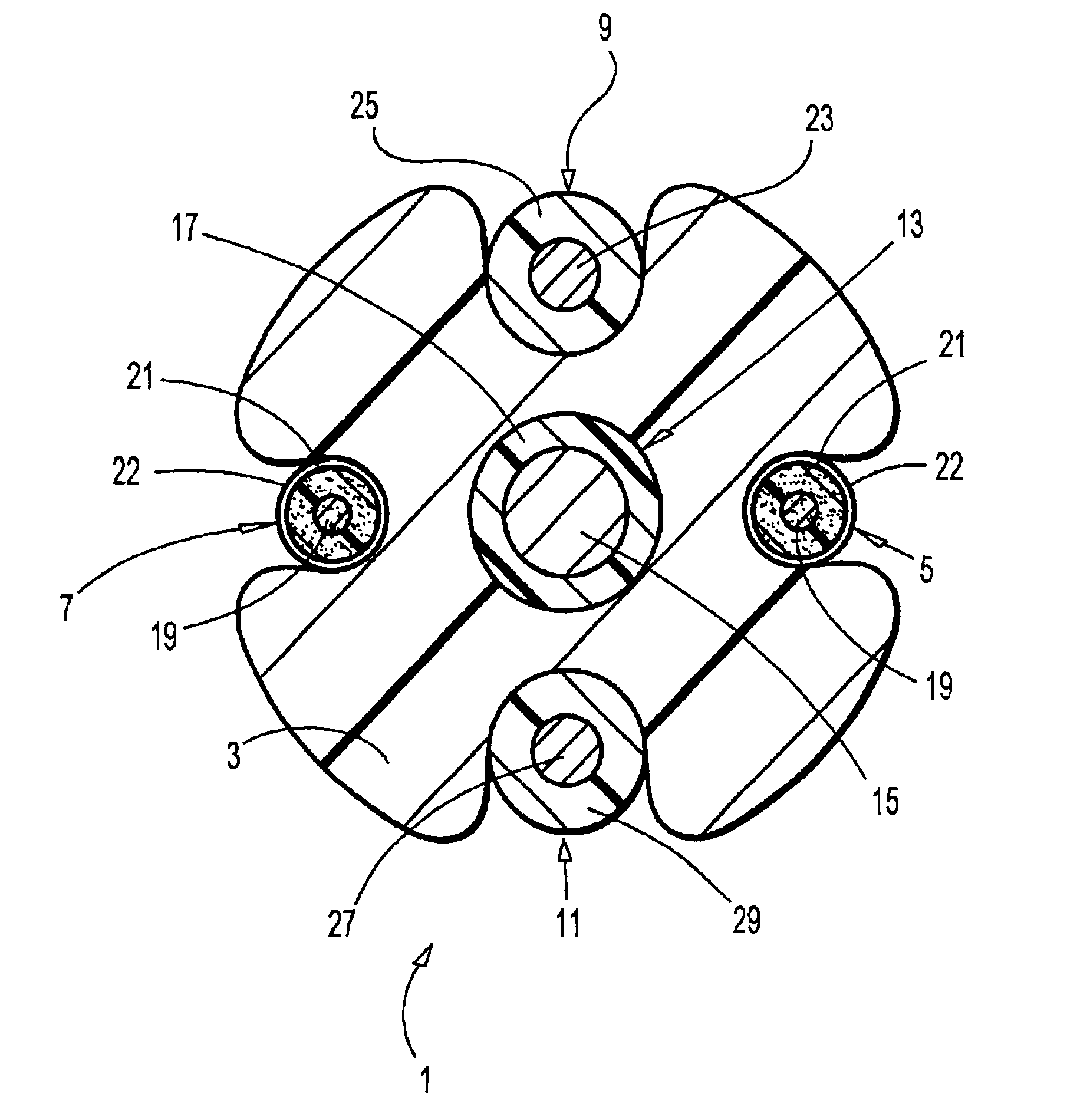
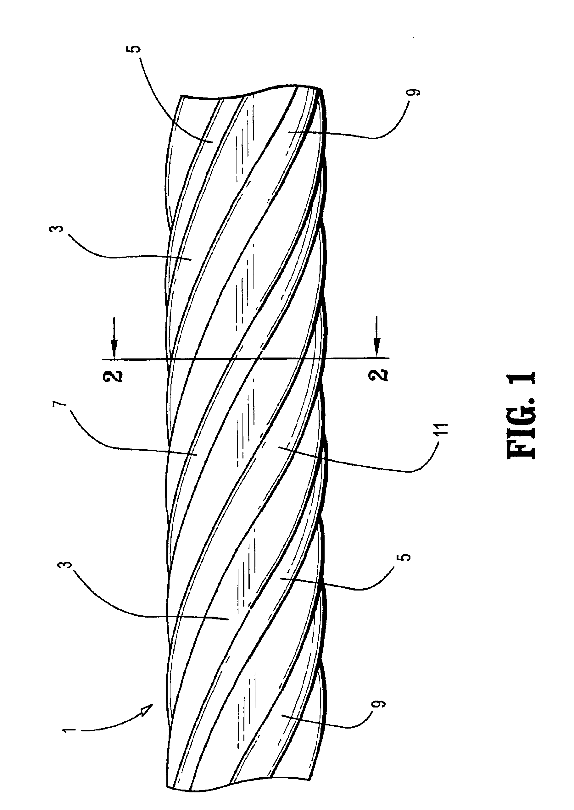
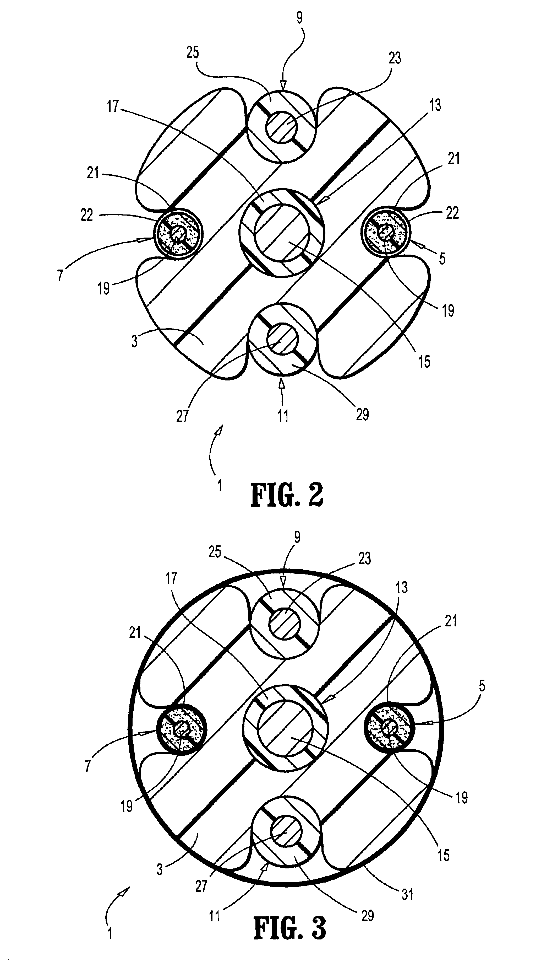
An alternate embodiment of the cable comprises first and second sensing wires and a core member around which the first and second sensing wires are wrapped. The first and second sensing wires and the core member are encapsulated by at least one non-conductive surface layer. The cable may further comprise insulating wires to assist in determining the exact location of the leak.

Problems solved by technology

Underground pipelines are subject to leakage from the piping, fittings, and valves.
Therefore, these sensor cables are subject to false alarms since such conventional sensor cables are not capable of differentiating between common conductive liquids such as ground water or rainwater containing mild concentrations of corrosive components and conductive, highly corrosive, liquids such as concentrated sulfuric acid, hydrochloric acid, nitric acid, acetic acid, strong mineral acids, or strong bases such as sodium hydroxide.

Method used


Image

  • Sensor cable
  • Sensor cable
  • Sensor cable

Examples


example 1

A sensing wire was prepared by extruding a layer of carbon-filled polyvinylidene fluoride (0.011 inch / 0.028 cm) over a first 30 AWG (0.010 inch / 0.025 cm diameter) solid Alloy 294 wire conductor. A second sensing wire was prepared in the same manner. An insulating wire was prepared by extruding a layer of polyvinylidene fluoride over a 24 AWG (0.025 inch / 0.064 cm diameter) solid tin-plated copper wire to give an outer diameter of approximately 0.054 inch (0.137 cm). A second insulating wire was prepared in the same manner. The polymer layers of the sensing wires and the insulating wires were then irradiated to 10 to 15 Mrad. The sensing wires were then dip coated in non-conductive polyurethane. Each of the sensing wires having a non-conductive surface layer had an outer diameter of approximately 0.036 inch (0.091 cm).

A central support member was prepared by extruding two layers of ethylene / tetrafluoroethylene copolymer to a total of 0.008 inch (0.020 cm) over a 16 AWG (0.060 inch / 0.1...

example 2

A sensing wire was prepared by extruding a first layer of carbon-filled polyvinylidene fluoride (0.011 inch / 0.028 cm) over a first 30 AWG (0.010 inch / 0.025 cm diameter) solid Alloy 294 wire conductor. A second sensing wire was prepared in the same manner. An insulating wire was prepared by extruding a layer of polyvinylidene fluoride over a 24 AWG (0.025 inch / 0.064 cm diameter) solid tin-plated copper wire to give an outer diameter of approximately 0.054 inch (0.137 cm). A second insulating wire was prepared in the same manner. The polymer layers of the sensing wires and insulating wires were then irradiated to 10 to 15 Mrad.

A central support member was prepared by extruding two layers of ethylene / tetrafluoroethylene copolymer to a total of 0.008 inch (0.020 cm) over a 16 AWG (0.060 inch / 0.152 cm) diameter stranded nickel-plated copper wire to give an outer diameter of approximately 0.077 inch (0.196 cm). Using a 1.5 inch (3.8 cm) extruder, a core member was prepared by extruding an...


PUM


Abstract

A cable suitable for detecting the presence of corrosive liquids is disclosed. In an embodiment the cable includes two sensing wires wrapped around a core member, at least one of the sensing wires being surrounded by a non-conductive surface layer. In an alternate embodiment the cable includes two sensing wires wrapped around a core member, the sensing wires and core member being encapsulated by a non-conductive surface layer. Preferably, the cable includes insulating wires for detecting the location of a leak. When a corrosive liquid contacts the sensing wires of the cable an electrical connection is created between them.

Description

FIELD OF THE INVENTIONThis invention relates to cables for sensing the presence of a corrosive liquid.BACKGROUND OF THE INVENTIONTransporting liquids such as crude oil, refined petroleum products, or corrosive liquids such as concentrated acids or bases is often accomplished utilizing tanks and underground pipelines. Underground pipelines are subject to leakage from the piping, fittings, and valves. When an underground pipe carrying a hazardous or corrosive liquid develops a leak, the leak must first be detected and located before it can be repaired.Various systems for detecting leaks are well-known. For example, sensor cables may be used to detect changes in variables along an elongate path, such as the presence of a liquid such as water, an organic solvent, or a corrosive liquid. Sensor cables may be extended in a pipeline, along the length or longitudinal axis or at various sections or points at which the leakage of liquids tends to occur.Known sensor cables generally comprise fi...

Claims


Application Information

Patent Timeline
IPC IPC(8): G01M3/16
CPCG01M3/165
Inventor MCCOY, KENNETH FERRELLWASLEY, ROBERT STEPHEN
Owner NVENT SERVICES GMBH
Learn More