
Organic PTC thermistor and making method

a thermistor and positive temperature technology, applied in the direction of resistive material coating, heat measurement, instruments, etc., can solve the problems of lack of reliability in long-term storage or the like, inability to provide satisfactory characteristics for protecting overcurrent or overheating, and the stability of thermoplastic polymer matrix tends to diminish initial resistance stability

Inactive Publication Date: 2004-08-17
TDK CORPARATION
View PDF17 Cites 32 Cited by
  • Summary
  • Abstract
  • Description
  • Claims
  • Application Information

AI Technical Summary

Benefits of technology

The pretreatment of conductive metal particle surfaces with an organic material prevents diffusion of oxygen into particle surfaces and hence, oxidation of particles during long-term storage, thereby stabilizing the resistance value. The surface treatment is also believed effective for preventing excessive agglomeration of conductive metal particles. Additionally, the surface treatment permits the conductive metal particles to be readily separated from the organic polymer matrix.

Problems solved by technology

In order to reduce the resistance of the thermistor, however, a large amount of conductive particles must be blended at the expense of rate of resistance change, failing to provide satisfactory characteristics for protecting overcurrent or overheating.
However, the inventors found that these organic PTC thermistors using conductive metal particles lack reliability in terms of long-term storage or the like.
Outside the range, a higher proportion of the thermoplastic polymer matrix tends to diminish the stability of initial resistance whereas a lower proportion tends to degrade the stability under hot humid conditions.
In the case of crystalline polymers, their melting point and hence, the operating temperature can be changed by altering their molecular weight or degree of crystallization or by copolymerizing with comonomers, but with a concomitant change of crystalline state which can lead to unsatisfactory PTC characteristics.
This problem becomes more outstanding when the operating temperature is set at 100.degree. C. or lower.
If this mixing proportion becomes lower or the content of the low-molecular weight organic compound becomes low, it may fail to provide a satisfactory resistance change rate.
Inversely, if this mixing proportion becomes higher or the content of the low-molecular weight organic compound becomes high, the thermistor body can be substantially deformed upon melting of the low-molecular weight organic compound and it may become awkward to mix with conductive metal particles.
Presumably such a protuberant surface contour allows for conduction of tunneling current flow and can reduce the room-temperature resistance as compared with smooth spherical conductive metal particles.
If this mixing ratio becomes low or the amount of the conductive metal particles becomes small, it may be difficult to make the room-temperature resistance in a non-operating state sufficiently low.
If the amount of the conductive metal particles becomes large, on the contrary, it may become difficult to obtain a high rate of resistance change and to achieve uniform mixing, failing to provide stable properties.
If an organic material can bond or interact with the matrix resin, it restrains the behavior of conductive metal particles, adversely affecting the restoring property from the operating state.
Such undesirable materials are, for example, organic acids and triazine derivatives.
When a polyolefin is used as the matrix resin, organic acids, especially long-chain saturated or unsaturated fatty acids are undesirable because carboxyl groups can adsorb to surfaces of the conductive metal particles and long-chain hydrocarbon moieties can interact with the matrix resin.
Too small an amount of the organic material may fail to achieve the desired property improving effect whereas too large an amount may make it difficult to fully diminish the resistance of the thermistor.

Method used


Image

  • Organic PTC thermistor and making method
  • Organic PTC thermistor and making method
  • Organic PTC thermistor and making method

Examples


example 1

The conductive metal particles used were filamentary nickel powder (trade name INCO Type 210 Nickel Powder by INCO Ltd.) having an average particle diameter of 0.5-1.0 .mu.m, an apparent density of 0.8 g / cm.sup.3, and a specific surface area of 1.5-2.5 m.sup.2 / g.

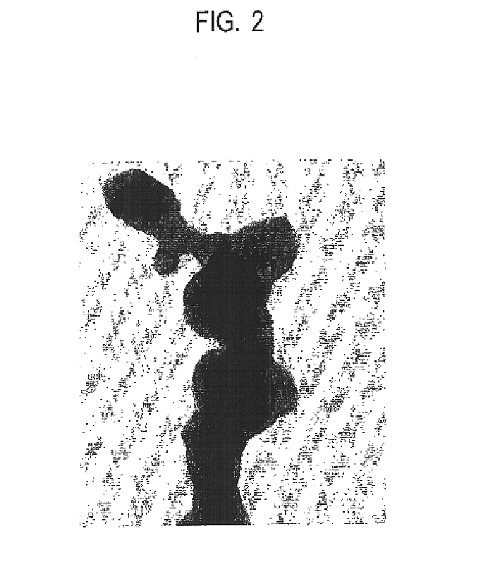
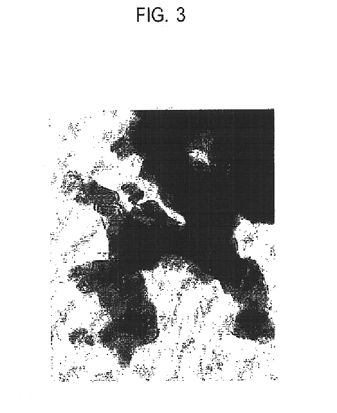
The nickel powder was dispersed in a 0.25% ethanol solution of polyethylene glycol (molecular weight 200, by Junsei Chemical Co., Ltd.), the amount of polyethylene glycol being 0.5% by weight based on the nickel powder, and agitated to form a slurry. Ethanol was evaporated off by means of an evaporator, leaving the surface treated nickel powder which was dried in vacuum. FIGS. 2 and 3 are TEM photomicrographs of the nickel powder before and after treatment.

A linear low-density polyethylene (trade name Evolue 2520 by Mitsui Chemicals, Inc., MFR 1.7 g / 10 min, mp 121.degree. C.) as the organic polymer matrix, the surface treated filamentary nickel powder, and paraffin wax (trade name Poly Wax 655 by Baker Petrolite, mp 99.degr...

example 2

A thermistor device was manufactured as in Example 1 except that polyglycerin (trade name Unigly G-2 by NOF Corp.) was used instead of the polyethylene glycol.

example 3

A thermistor device was manufactured as in Example 1 except that tetradecanol (trade name NAA-43 by NOF Corp., mp 38.degree. C.) was used instead of the polyethylene glycol.


PUM

PropertyMeasurementUnit
vapor pressureaaaaaaaaaa
operating temperatureaaaaaaaaaa
temperatureaaaaaaaaaa

Abstract

In an organic PTC thermistor comprising an organic polymer matrix and conductive metal particles dispersed therein, the conductive metal particles are pretreated with an organic material which is different from the organic polymer matrix, does not covalently bond with the conductive metal particles, and is not compatible at a molecular level with the organic polymer matrix so that an organic material layer covers surfaces of conductive metal particles whereby the stability of thermistor performance is improved.

Description

1. Field of the InventionThis invention relates to an organic positive temperature coefficient thermistor that is used as a temperature sensor or overcurrent-protecting element, and has positive temperature coefficient (PTC) of resistivity characteristics that its resistance value increases with increasing temperature.2. Background ArtAn organic positive temperature coefficient thermistor having conductive particles dispersed in a polymer matrix is well known in the art, as disclosed in U.S. Pat. Nos. 3,243,753 and 3,351,882.The increase in the resistance value is believed to be due to the expansion of the crystalline polymer upon melting, which in turn cleaves a current-carrying path formed by the conductive fine particles.An organic PTC thermistor can be used as an overcurrent or overheat-protecting element, a self-regulating heater, and a temperature sensor.Of these, the overcurrent or overheat-protecting element in series connection with an electric circuit requires a sufficient...

Claims


Application Information

Patent Timeline
Patent Type & Authority Patents(United States)
IPC IPC(8): C08K3/00C08K3/08G01K7/22G01K7/16H01C17/065H01C7/02H01C17/06
CPCC08K3/08G01K7/22H01C7/027H01C17/06513G01K7/226Y10T428/31Y10T428/249921Y10T428/31504Y10T428/31511Y10T428/31522
Inventor HANDA, TOKUHIKOYOSHINARI, YUKIE
Owner TDK CORPARATION
Learn More