
Process for preparing an anode catalyst for fuel cells and the anode catalyst prepared therewith

a fuel cell and anode catalyst technology, applied in the direction of catalyst activation/preparation, metal/metal-oxide/metal-hydroxide catalysts, etc., can solve the problems of high cost of hydrogen, poor reaction efficiency, and high toxicity of traditional platinum catalysts, so as to improve the quality of the reduction process and high activity , the effect of high tolerance to carbon monoxid

Inactive Publication Date: 2004-09-28
UMICORE AG & CO KG
View PDF15 Cites 38 Cited by
  • Summary
  • Abstract
  • Description
  • Claims
  • Application Information

AI Technical Summary

Benefits of technology

The catalyst exhibits improved carbon monoxide tolerance, maintaining high performance even at elevated CO concentrations and zero air-bleed conditions, with ruthenium predominantly in a metallic state, enhancing fuel cell efficiency and reducing environmental impact.

Problems solved by technology

Currently, however, hydrogen is still too expensive and causes problems with regard to storage and the refuelling of vehicles.
Traditional platinum catalysts are very sensitive to poisoning by carbon monoxide.
This applies in particular to PEM fuel cells which, with low working temperatures of up to 100.degree. C., are especially sensitive to poisoning by carbon monoxide.
Even larger problems occur with DMFC systems.
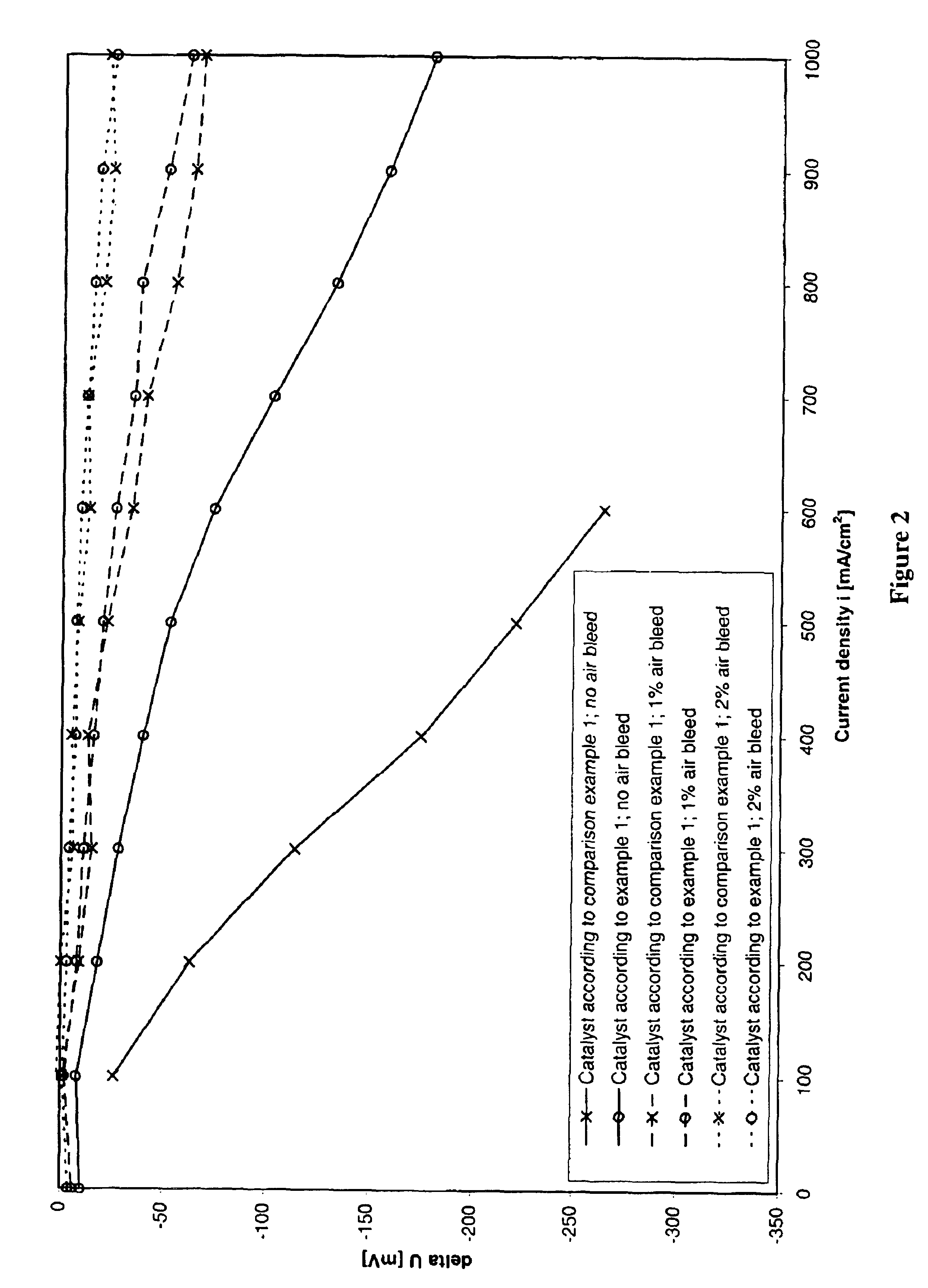
The use of an air-bleed leads, in addition to the oxidation of carbon monoxide, to the oxidation of some of the hydrogen, and thus, reduces the efficiency of the overall system.
In addition, preparation using the colloids described is costly.
At the high operating temperatures of the phosphoric acid fuel cell, however, the tendency of carbon monoxide to be adsorbed onto metal surfaces is lower in any case than at the low operating temperatures of a PEM fuel cell.
However, this catalyst is not an alloy catalyst because adsorption of carbon monoxide on the metal particles during deposition prevents the formation of an alloy.
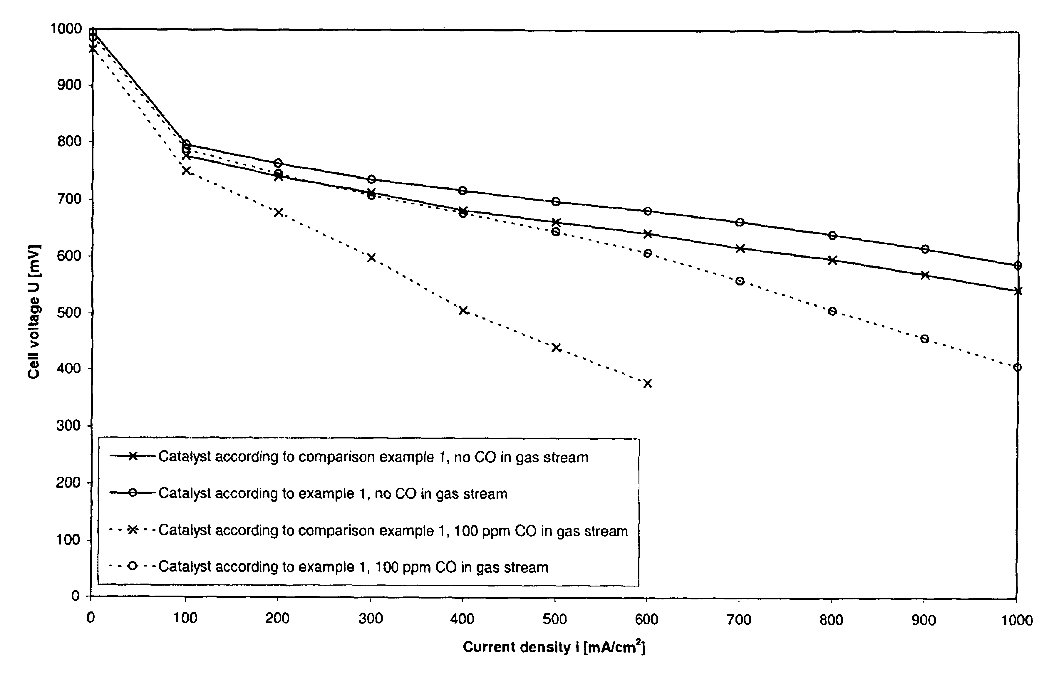
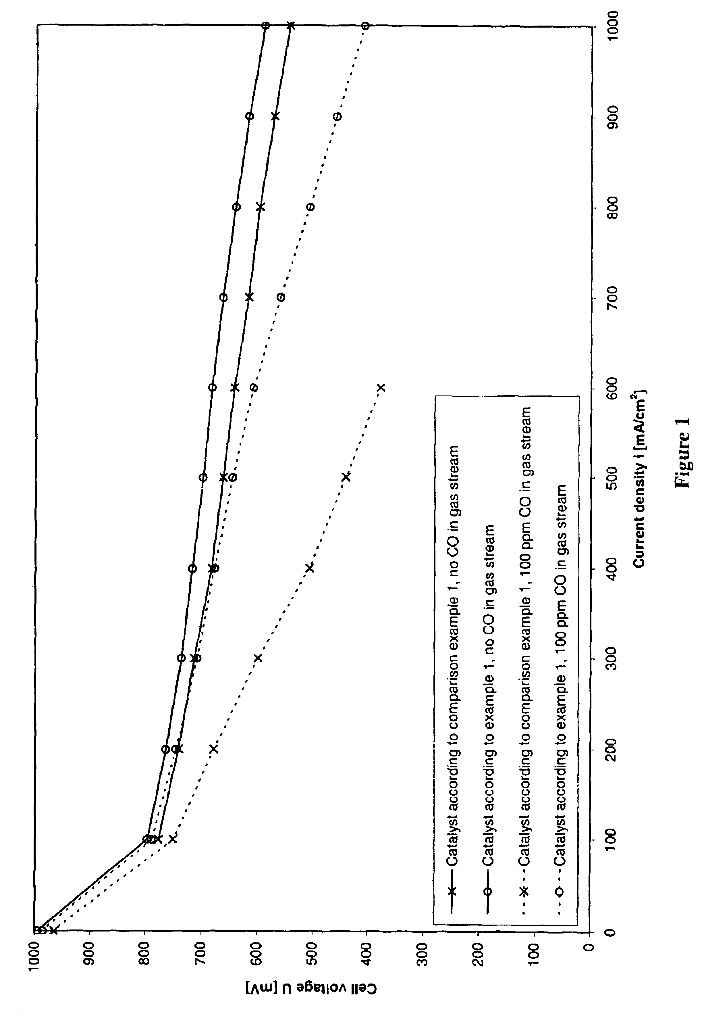
Tests using a catalyst of this type (40 wt.-% PtRu on Vulcan XC 72) revealed an unsatisfactory tolerance to carbon monoxide, especially at concentrations of carbon monoxide of more than 100 ppm in the anode gas.
This is still far too high for practical operation.
However, this method of preparation raises problems with regard to protection of the environment and health (formation of large amounts of nitrous gases, working with liquid, corrosive melts).

Method used


Image

  • Process for preparing an anode catalyst for fuel cells and the anode catalyst prepared therewith
  • Process for preparing an anode catalyst for fuel cells and the anode catalyst prepared therewith
  • Process for preparing an anode catalyst for fuel cells and the anode catalyst prepared therewith

Examples


example 1

30 g of carbon black (Vulcan XC 72) were suspended in 1.5 l of fully deionised water (VE water) for 30 minutes at room temperature. 52.7 g of 25% strength hexachloroplatinic (IV) acid and 29.4 g of 23.2% strength ruthenium (III) chloride solution were diluted to 300 ml with fully deionised water (VE water) and added to the suspension. The suspension was heated to 80.degree. C. Then the pH was increased to 7.0 using caustic soda solution.

After intensive stirring, 320 ml of dipotassium tartrate hemihydrate solution (Merck, Darmstadt, concentration 0.1 mol / l) were added to the suspension. The pH was kept constant by the further addition of caustic soda solution. Then 56 ml of 24% strength hydrazine solution were added and the suspension was stirred again. Then the catalyst was filtered off and dried at elevated temperature. Finally, the catalyst was calcined at 500.degree. C. under nitrogen.

The final catalyst had a noble metal loading of 40 wt.-%, with respect to the total weight, and ...

example 2

To prepare a catalyst with a noble metal loading of 60 wt.-%, example 1 was repeated, but only 13.3 g of carbon black were suspended in water in order to obtain a higher loading.

The final catalyst had a noble metal loading of 60 wt.-%, with respect to the total weight, and an atomic ratio Pt / Ru of 1:1. Characterisation of the catalyst using XRD and XPS gave the following values:

example 3

To prepare an unsupported platinum-ruthenium catalyst (platinum-ruthenium black), the following procedure was used:

52.7 g of 25% strength hexachloroplatinic(IV) acid and 29.4 g of 23.2% strength ruthenium (III) chloride solution were added to 1.8 l of fully deionised water (VE water) and the solution was heated to 80.degree. C. Then, the pH was increased to 7.0 using caustic soda solution.

After intensive stirring for a period of 1.5 hours, 320 ml of dipotassium tartrate hemihydrate solution (Merck, Darmstadt, concentration 0.1 mol / l) were added. The pH was kept constant by the further addition of caustic soda solution. Then 56 ml of 24% strength hydrazine solution were added and the suspension was stirred further. Then the catalyst was filtered off and dried at elevated temperature.

Characterisation of the catalyst using XPS and XRD gave the following values:


PUM

PropertyMeasurementUnit
bonding energyaaaaaaaaaa
particle sizeaaaaaaaaaa
temperaturesaaaaaaaaaa

Abstract

The invention provides a process for preparing a platinum-ruthenium catalyst and the catalyst prepared therewith. The catalyst can be supported on a support material in powder form or may also be unsupported. To prepare the supported catalyst, the support material is suspended in water and the suspension is heated to at most the boiling point. While keeping the temperature of the suspension the same, solutions of hexachloroplatinic acid and ruthenium chloride are then added to the suspension, then the pH of the suspension is increased to a value between 6.5 and 10 by adding an alkaline solution and the noble metals are thus precipitated onto the support material. Afterwards, one or more organic carboxylic acids and / or their salts are added to the suspension and the catalyst is chemically reduced, washed, dried and optionally subsequently calcined under an inert or reducing atmosphere at a temperature between 300 und 1000° C. The catalyst is characterised by a high tolerance to carbon monoxide poisoning in the fuel cell.

Description

The invention provides a platinum-ruthenium catalyst for PEM fuel cells with a high tolerance toward poisoning by carbon monoxide. The catalyst is particularly suitable as an anode catalyst for fuel cells with a polymer electrolyte membrane (PEM fuel cells), but it is also suitable as an anode catalyst for direct methanol fuel cells (DMFC).BACKGROUND OF INVENTIONIn principle, fuel cells are gas-operated batteries in which the energy obtained from the reaction of water and oxygen is converted directly into electrical energy. The present invention describes catalysts for PEM fuel cells (PEM=polymer electrolyte membrane) that are suitable for operation with hydrogen-containing gases or with methanol (DMFC=direct methanol fuel cell). The first-mentioned type of fuel cell is gaining in importance as a source of power for motor vehicles operated by electric engines, due to its high energy density and robustness, the latter type of fuel cell enables a reduction in the number of units requi...

Claims


Application Information

Patent Timeline
Patent Type & Authority Patents(United States)
IPC IPC(8): B01J23/40B01J37/00B01J37/03H01M4/90H01M4/92B01J23/42B01J23/46H01M4/86H01M4/88H01M8/10
CPCB01J23/40B01J37/03H01M4/926H01M4/928H01M4/921B01J23/42B01J23/462Y02E60/50H01M2004/8684B01J23/46
Inventor RUTH, KARSTENBIBERBACH, PETERSTARZ, KARL-ANTONMCINTOSH, RALPH
Owner UMICORE AG & CO KG
Learn More