Exhaust gas recirculation system having cooler

a technology of exhaust gas recirculation and cooler, which is applied in the direction of mechanical equipment, machines/engines, electric control, etc., can solve the problems of reducing heat exchange efficiency and cooling performan

Inactive Publication Date: 2004-12-07
DENSO CORP
View PDF9 Cites 109 Cited by
  • Summary
  • Abstract
  • Description
  • Claims
  • Application Information

AI Technical Summary

Benefits of technology

Thus, the EGR cooler can maintain excellent heat-exchanging performance even if the EGR cooler is used for a long time. As a result, an emission-reducing effect is maintained for a long time.

Problems solved by technology

However, if the EGR system is used for a long time, soot or unburned hydrocarbon included in the EGR gas may adhere and deposit onto a heat exchanging part of the EGR cooler.
The deposition of the soot or the hydrocarbon decreases heat-exchanging efficiency and cooling performance.

Method used


Image

  • Exhaust gas recirculation system having cooler
  • Exhaust gas recirculation system having cooler
  • Exhaust gas recirculation system having cooler

Examples


first embodiment

(First Embodiment)

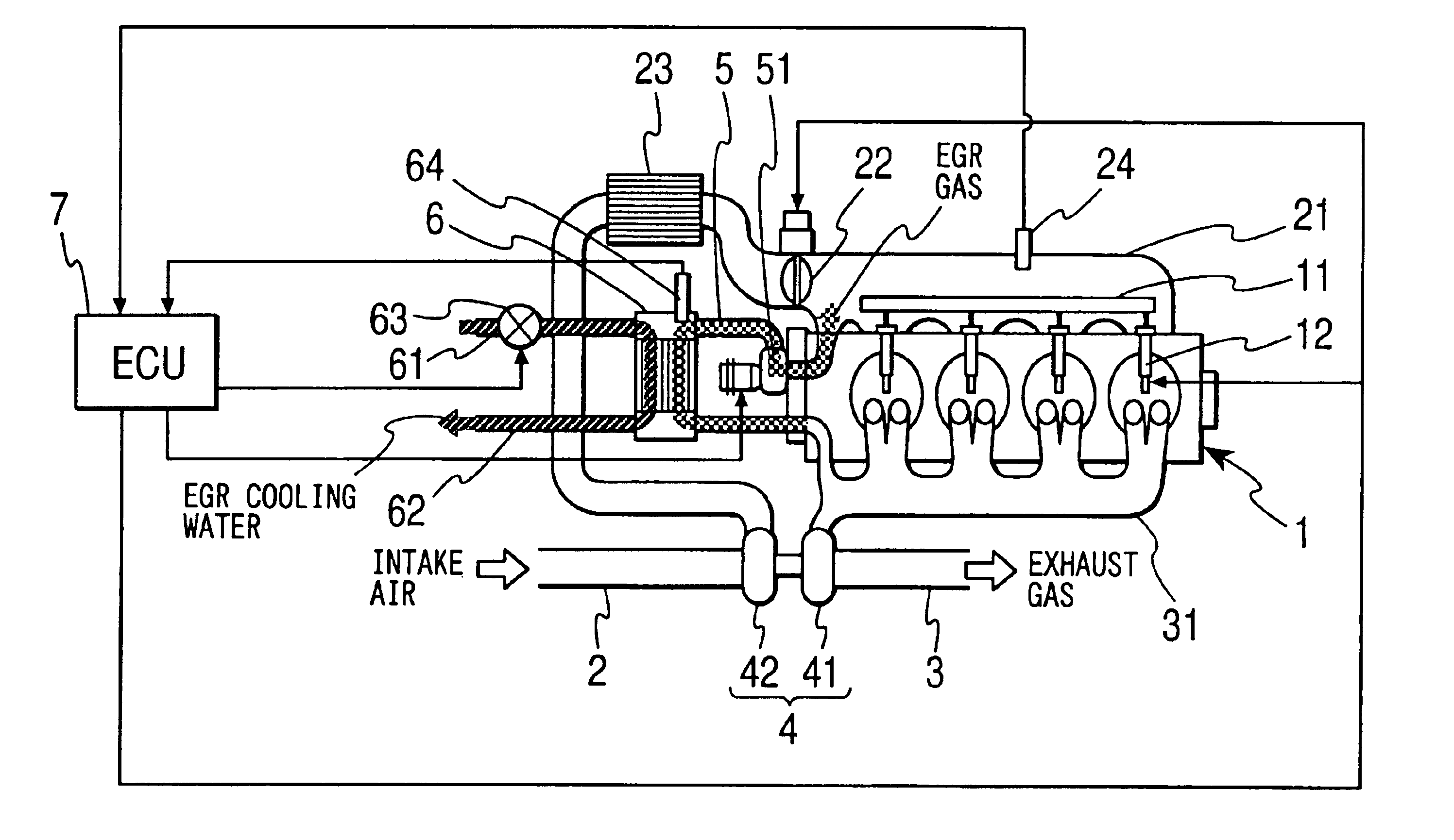
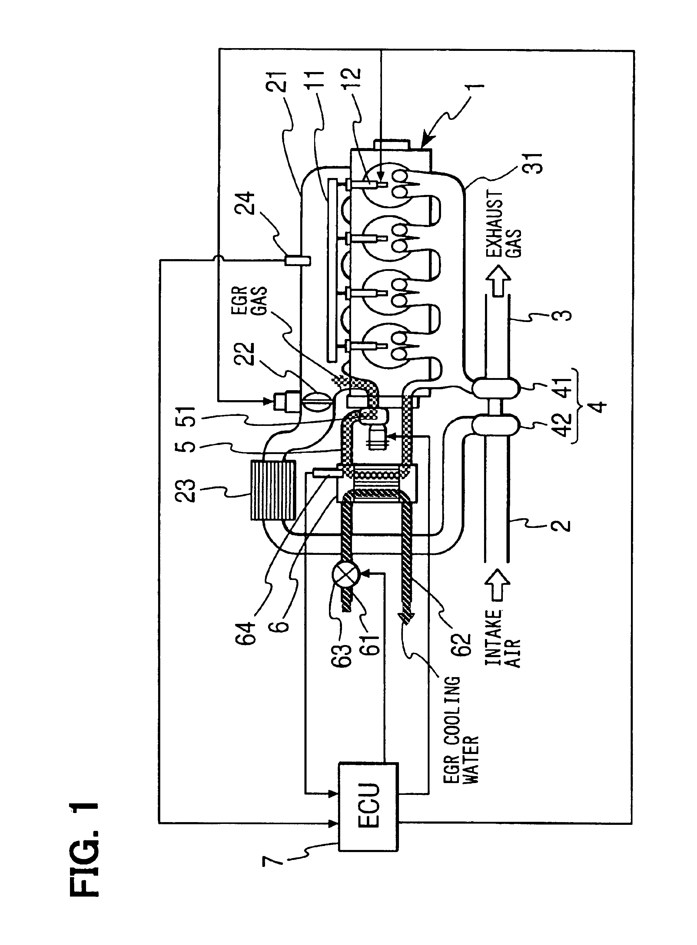
Referring to FIG. 1, an engine 1 having an exhaust gas recirculation system according to the first embodiment is illustrated. The engine 1 has a common rail 11, which is common to respective cylinders of the engine 1, and fuel injection valves 12. Each fuel injection valve 12 is connected with the common rail 11 and injects fuel into a combustion chamber of each cylinder of the engine 1. An intake manifold 21 of the engine 1 is connected with an intake pipe 2. An intake throttle 22 is disposed at the connection between the intake manifold 21 and the intake pipe 2. The intake throttle 22 regulates a flow rate of intake air.

An exhaust manifold 31 of the engine 1 is connected with an exhaust pipe 3. A turbine 41 of a centrifugal supercharger 4 is disposed in the exhaust pipe 3. A compressor 42 is disposed in the intake pipe 2. The turbine 41 is connected with the compressor 42 through a turbine shaft. The turbine 41 is driven with the use of thermal energy of the exha...

second embodiment

(Second Embodiment)

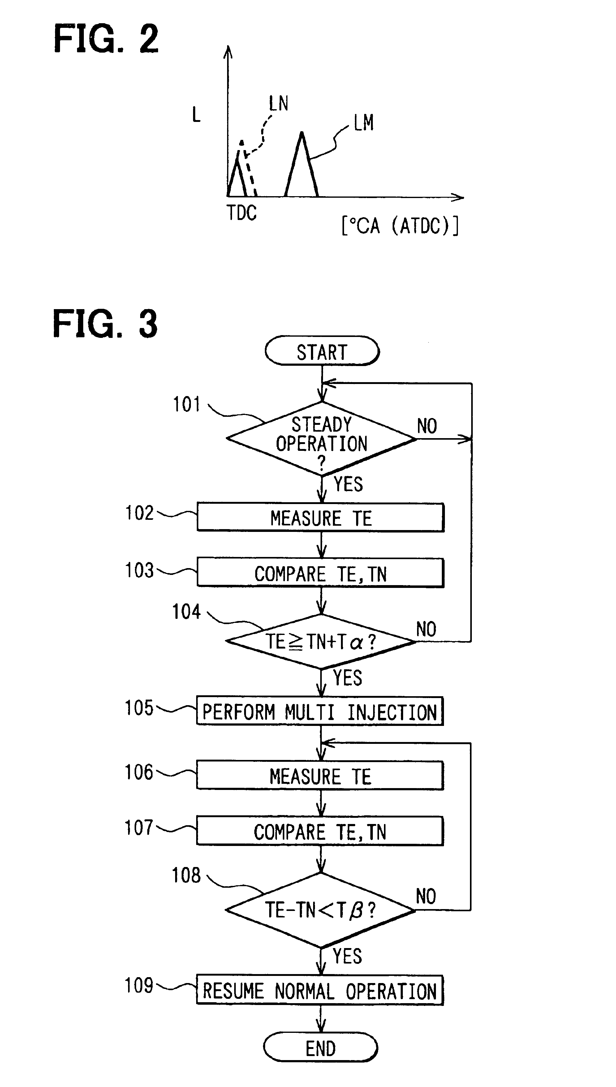
An internal combustion engine 1 having an EGR system according to the second embodiment is illustrated in FIGS. 4A, 4B and 5. In the EGR system according to the second embodiment, the intake throttle 22 is rotated toward a closing direction from a usual position when the exhaust gas is heated to regenerate the cooling performance of the EGR cooler 6 as shown in FIGS. 4A and 4B. FIG. 4A shows a state in which the intake throttle 22 is at the usual position. FIG. 4B shows a state in which the intake throttle 22 is rotated toward the closing direction from the usual position. Thus, the flow rate of the intake air is decreased and thermal capacity of the gas entering the combustion chamber of the engine 1 is reduced. As a result, the exhaust gas is heated to a temperature at which the soot and the unburned hydrocarbon are oxidized and eliminated.

Next, a processing performed by the ECU 7 according to the second embodiment will be explained based on a flowchart shown in...

third embodiment

(Third Embodiment)

An internal combustion engine 1 having an EGR system according to the third embodiment is illustrated in FIGS. 6 and 7. In order to increase the temperature in the EGR cooler 6 and to regenerate the cooling performance, the EGR system according to the third embodiment delays the fuel injection timing from the usual injection timing as shown in FIG. 6. A broken line LN in FIG. 6 shows a nozzle lifting degree of the fuel injection nozzle at the usual fuel injection timing and a solid line LD in FIG. 6 shows the nozzle lifting degree at the delayed fuel injection timing. In this case too, like the case of the multi-injection, part of combustion energy is converted into the thermal energy of the exhaust gas (not into the motive energy). As a result, the temperature of the exhaust gas is increased and the soot or the unburned hydrocarbon is eliminated by the oxidization.

Next, a processing performed by the ECU 7 according to the third embodiment will be explained based o...


PUM


Abstract

An exhaust gas recirculation (EGR) system of an internal combustion engine has an EGR cooler in an EGR passage connecting an exhaust manifold with an intake manifold. The EGR cooler cools EGR gas recirculated through the EGR passage. Cooling performance detecting means included in an electronic control unit (ECU) determines that cooling performance of the EGR cooler is degraded when intake pressure measured by an intake pressure sensor is lower than a normal intake pressure by at least a predetermined value. When the degradation of the cooling performance is detected, cooling performance regeneration controlling means included in the ECU increases the temperature inside the EGR cooler by heating the exhaust gas to eliminate soot or unburned hydrocarbon by oxidization. Thus, the cooling performance of the EGR cooler is regenerated.

Description

1. Field of the InventionThe present invention relates to an exhaust gas recirculation (EGR) system having an EGR cooler in an EGR passage, through which part of exhaust gas is recirculated to an intake passage. The EGR cooler cools the recirculated exhaust gas.2. Description of Related ArtAn exhaust gas recirculation system (EGR system) is commonly used for reducing emission of a diesel engine. The EGR system recirculates part of exhaust gas to an intake passage. EGR gas, which is the exhaust gas recirculated to the intake passage, includes much inert gas such as vapor or carbon dioxide, which is generated in combustion. An advantage of the EGR system is that generation of nitrogen oxide is inhibited because combustion temperature is decreased. If an EGR cooler is disposed in an EGR passage for cooling the EGR gas, charging efficiency of the EGR gas is improved, and the emission-reducing effect is further improved.However, if the EGR system is used for a long time, soot or unburned...

Claims


Application Information

Patent Timeline
Patent Type & Authority Patents(United States)
IPC IPC(8): F02D41/02F02M25/07F02D9/02F02D21/08F02D41/04F02D41/38F02D41/40F02D45/00
CPCF02D41/021F02M25/0702F02M25/0754F02M25/0737F02M25/074F02M25/0701F02M25/0707F02M26/05F02M26/50F02M26/49F02M26/32F02M26/35F02M26/47
Inventor YAHATA, SHIGETOSAITO, MAKOTOKINUGAWA, MASUMISEKIGUCHI, KIYONORIKUBOSHIMA, TSUKASA
Owner DENSO CORP
Why Eureka
Try Eureka