
Glass fiber fixative and fixing process

a technology of glass fibers and fixatives, applied in the direction of optical elements, manufacturing tools, instruments, etc., can solve the problems of reducing the strength of fibers, reducing the adhesion properties of optical fibers and non-glass materials, and consuming metallisation processes, so as to reduce the damage to nearby fiber coatings, and select the softening and melting points

Inactive Publication Date: 2005-01-04
LUMENTUM TECH UK LTD
View PDF10 Cites 31 Cited by
  • Summary
  • Abstract
  • Description
  • Claims
  • Application Information

AI Technical Summary

Benefits of technology

[0045]The invention exploits the ferromagnetic characteristic of materials such as Kovar to used induction heating as a means of locally heating a glass preform provided to bond a glass material element in an optical assembly and a non-glass material element. The induction heating advantageously enables the preform to melt to form a hermetic seal between the ferromagnetic material and glass material without unduly heating other portions of the optical assembly.
[0046]The use of a glass fixative for forming hermetic seals is advantageous as this removes the need to metalise optical fibers. This is advantageous as it obviates the weakening of the optical fibers associated with the metalisation process.
[0048]The composition of the glass fixative is selected so that the thermal expansion coefficient, viscosity, adhesive characteristics and melting point of the glass fixative fall within desired ranges. The ability to select the softening and melting points of the glass fixative is advantageous. A series of bonds can be formed in relatively close proximity to each other, providing the melting point of each successive bond is sufficiently raised above the temperature at which earlier bond(s) soften. The formation of a series of bonds in the vicinity of each other is further enhanced when localized heating is used to melt the glass preforms forming the bond.
[0049]Advantageously, the glass fixative may melt at a temperature below 400° C. Such low processing temperatures and localized heating help to mitigate damage to the nearby fiber coating, particularly when the coating is formed from a plastic material such as acrylic and Hytrel™.
[0050]Advantageously, localized heating to be provided such that forming a subsequent bond in the vicinity of an earlier bond results in less thermal stress on the earlier bond. The localized heating method results in the optical bond stressing the optical fiber such that it is bonded in a compressive state. This enhances the ability of the bonded fiber to withstand shock and vibration.
[0051]Advantageously, the glass preform can be stamped into an annular shape to facilitate positioning of the glass fixative around the optical fiber to be bonded. Advantageously, the melting point of the glass perform and the viscosity of the molten glass are sufficiently low to enable the melted glass to flow to form an extended bonding area.

Problems solved by technology

Several problems are associated with the bonding process between a glass material and a non-glass material generally, and the high design specifications for optical components exacerbate these problems.
Determining the composition of a glass fixative having a sufficiently low melting point to enable an optical fiber to be bonded to a non-glass material without deforming the optical fiber, having a desired thermal coefficient of expansion, and good adhesive properties to both the silica of the optical fiber and the non-glass material is a difficult and complex task.
Such metallisation processes are time consuming and the fiber strength can be significantly reduced as a result (typically for example by 30%).
Other disadvantages include the extensive handling of fibers required by such processes and the associated high fiber breakage rate, and the capital expenditure on plant required by such processes.
A further disadvantage of metalisation processes for fiber fixing is that the soldering process can leave behind potentially corrosive fluxes.
The preparation of the fibers for metallisation and soldering is moreover time-consuming.
Yet another disadvantage of fiber fixing using metalisation processes is that no reworking is possible during either the metalisation or soldering stages.
In complex optical components, a further problem is the necessity of preventing preexisting bonds from being degraded when subsequent bonds are formed in the near vicinity.

Method used


Image

  • Glass fiber fixative and fixing process
  • Glass fiber fixative and fixing process
  • Glass fiber fixative and fixing process

Examples


Embodiment Construction

[0057]There will now be described by way of example the best mode contemplated by the inventors for carrying out the invention. In the following description numerous specific details are set forth in order to provide a thorough understanding of the present invention. It will be apparent however, to one skilled in the art, that the present invention may be practiced without limitation to these specific details. In other instances, well known methods and structures have not been described in detail so as not to unnecessarily obscure the present invention.

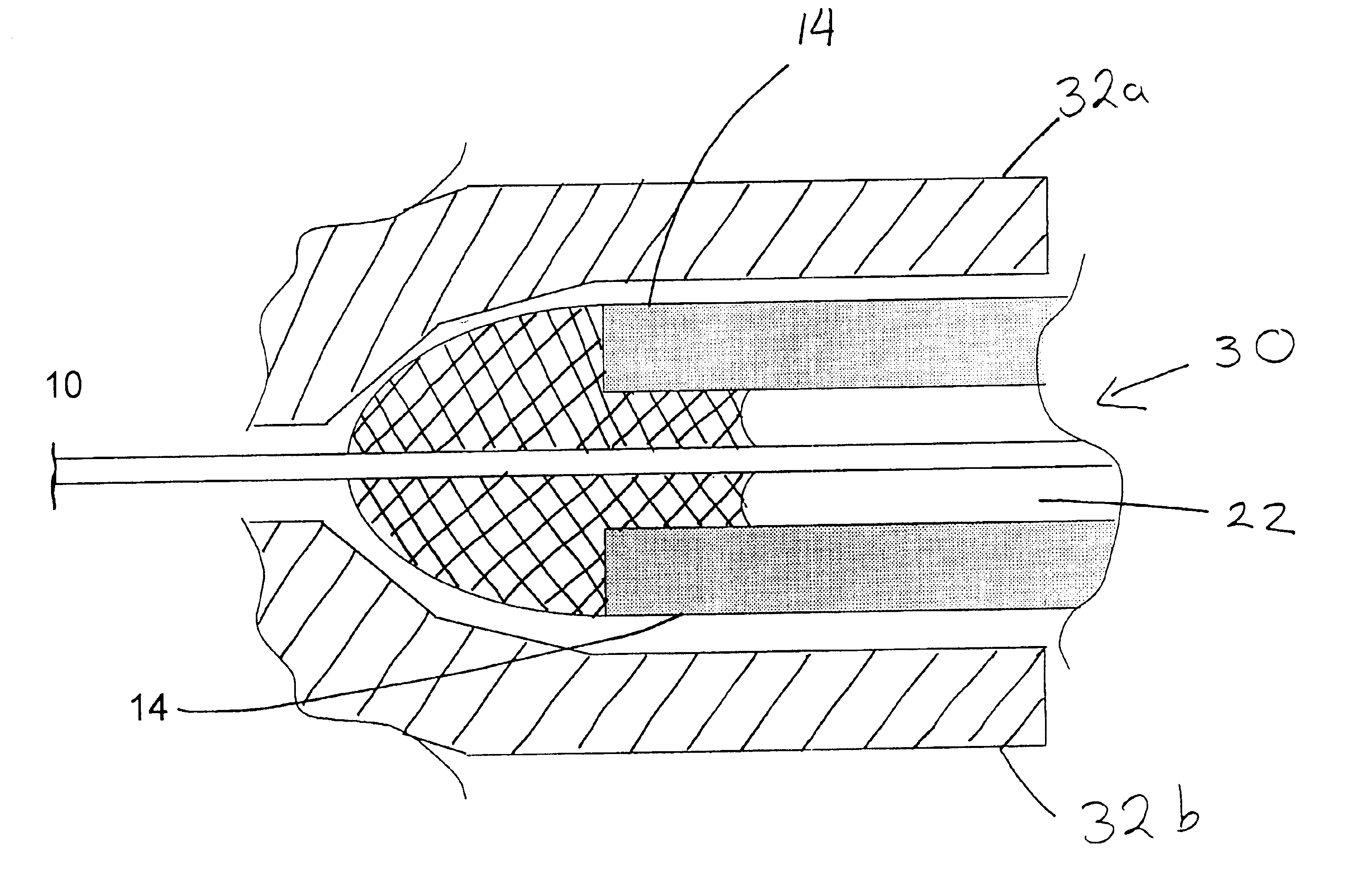
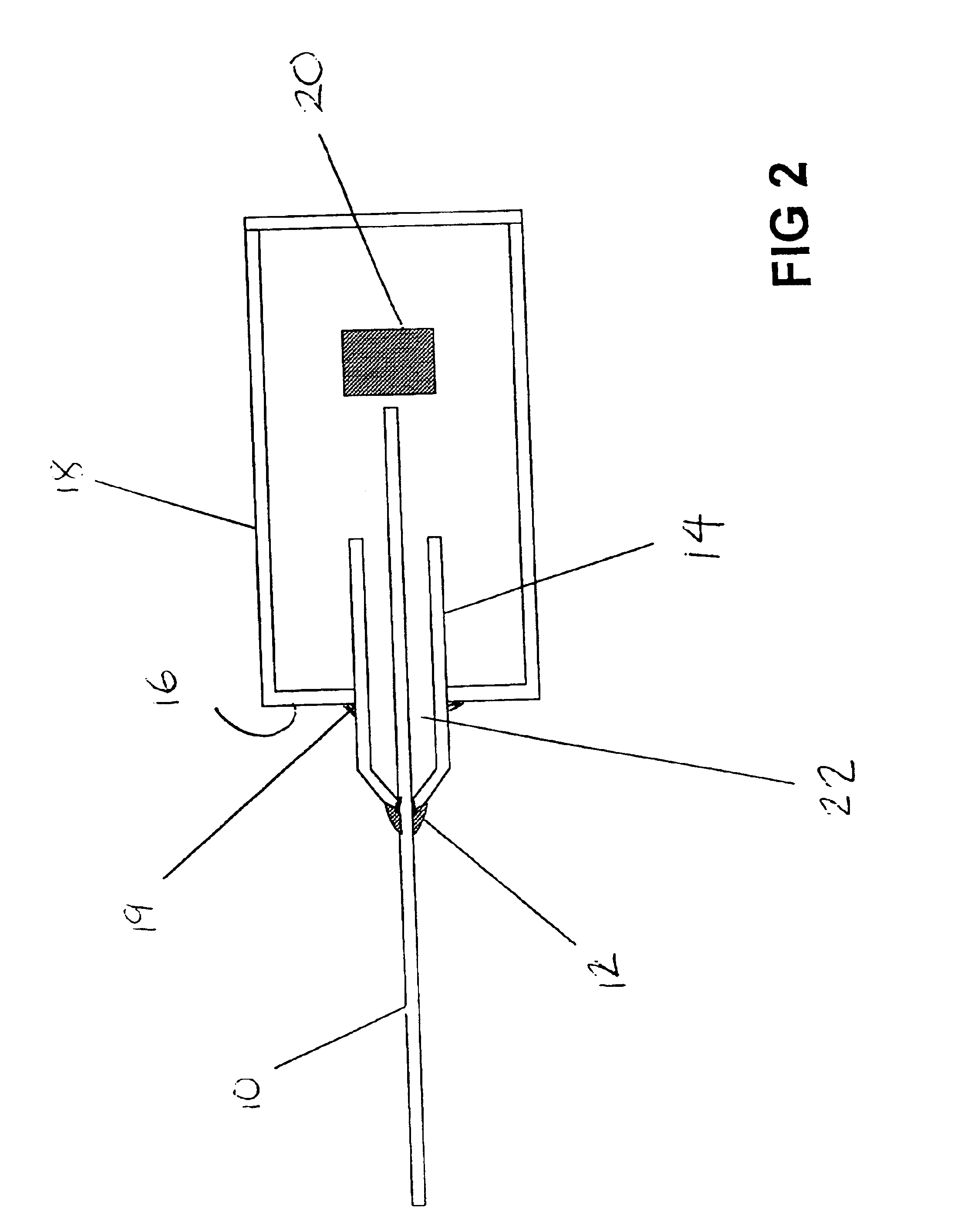
[0058]Referring now to FIG. 2 of the accompanying drawings, a glass element, here an optical fiber 10 is bonded by a glass fixative bond 12 to a non-glass material element, here a hypo tube 14. The hypo tube 14 is comprises a non-glass material, for example Kovar, which is a nickel / iron alloy. In other embodiments of the invention other materials may be wish to be bonded to the optical fiber.

[0059]The hypo tube 14 is bonded to walls 1...


PUM

PropertyMeasurementUnit
Viscosityaaaaaaaaaa
Adhesion strengthaaaaaaaaaa
Melting pointaaaaaaaaaa

Abstract

A glass fixative composition for bonding glass materials to non-glass materials is provided. The fixative composition is selected for its thermal expansion coefficient, its viscosity, its adhesion to glass, melting point, and bond strength. The glass fixative is in particular useful for bonding optical fibers to metallic materials such as Kovar. The low melting point of the glass fixative enables localized heating methods to be used, in particular, as Kovar is a ferromagnetic material, induction heating can be used to form a bond. The bond formed provides a compressive joint which enables the fiber to be hermetically fixed in position.

Description

BACKGROUND OF THE INVENTION[0002]This invention relates to an fixative for glass fibers and to a glass fiber fixing process. The fixing process and fixative enable glass fibers such as are commonly used in optical communications components to be fixed in position with a hermetic seal.[0003]Optical fibers are relatively thin, fragile strands of glass along which an optical signal propagates. For example, see FIG. 1 of the accompanying drawings for a cross-section of a typical optical fiber. An optical fiber 2 typically comprises an glass fiber core 4 covered by a glass cladding material 6. Typically a primary coating 8a, and secondary outer coating 8b are then used to protect the fiber. The outer coating protects the glass fiber and increases the robustness of the optical fiber.[0004]These outer coatings are typically formed from polymeric materials which have low melting points relative to the glass cladding and core, for example acrylic materials and materials such as thermoplastic...

Claims


Application Information

Patent Timeline
IPC IPC(8): C03C8/00C03C8/24G02B6/42
CPCG02B6/4248C03C8/245
Inventor SNOWDON, KENNETHDURRANT, TIMOTHY JWILMSHURST, RICHARDTANNER, CHRISTOPHER G
Owner LUMENTUM TECH UK LTD
Learn More