
Hybrid electric vehicle incorporating an integrated propulsion system

a hybrid electric vehicle and propulsion system technology, applied in hybrid vehicles, secondary cell servicing/maintenance, cell components, etc., can solve the problems of incomplete utilization of active materials, poor performance of early ordered materials, etc., to achieve excellent cycle life, high peak power, and high energy density

Inactive Publication Date: 2005-01-04
CHEVRON TEXACO TECH VENTURES
View PDF34 Cites 21 Cited by
  • Summary
  • Abstract
  • Description
  • Claims
  • Application Information

AI Technical Summary

Benefits of technology

"The present invention provides a power system for a hybrid vehicle that combines high peak power and high energy density. This is achieved by using NiMH batteries that have a unique combination of properties, including high power, low depth of discharge cycle life, good thermal management, and excellent gas recombination. The invention also provides an integrated propulsion system that maximizes the efficiency of the combustion engine and electric motor, and provides charging current for the batteries through regenerative braking and a power controlling system. The battery design includes a porous metal substrate with current collection lines for high conductivity, and the current collecting tab may be laser welded for increased conductivity. The invention also includes low pressure nickel metal hydride electrochemical cells for the batteries."

Problems solved by technology

The performance of the early ordered materials was poor, but in the early 1980's, as the degree of modification increased (that is as the number and amount of elemental modifiers increased), their performance began to improve significantly.
However, quadrivalent nickel is also involved in the nickel hydroxide redox reaction, the utilization of which has never been investigated.
One reason for this is incomplete utilization of the active material due to electrical isolation of oxidized material.
In addition, the duty cycle of a peak power application requires exceptional cycle life at low depths of discharge, particularly in charge depleting systems.
On the other hand, batteries used in HEVs will be subjected to many rapid charge and discharge cycles during normal operation.
Such rapid charging and discharging will result in significant thermal swings that can affect the battery performance.
In particular, the application notes that because heat conduction perpendicular to electrode plates is 10-20 times smaller than conduction parallel to electrode plates, cells using flat electrodes must be modified significantly which makes them unacceptably heavy.
None suggest how this can be accomplished without modifications that, as U.S. Pat. No. 4,115,630 specifically states, result in an unacceptable addition to the total weight of the cell.
In all sealed cells, the discharge capacity of a nickel based positive electrode is limited by the amount of electrolyte, the amount of active material, and charging efficiency.
The charge capacity of a NiMH negative electrode is limited by the amount of active material used, since its charge efficiency is very high, nearly a full state of charge is reached.
This becomes a critical problem for batteries in any HEV system that undergo repetitive charge and discharge cycles.
While many GCEs are very efficient, their presence decreases the area available for active electrodes and hence decreases the overall volumetric energy density of the cell.
Given the fundamental differences in requirements between the EV and those for an HEV application, it could be expected that those batteries currently optimized for use in EV applications will generally not be suitable for HEV without increasing power density.
While the demonstrated performance of Ovonic EV batteries has been impressive, these cell and battery designs have been optimized for use in pure EVs and therefore do not meet the specific requirements for HEVs.

Method used


Image

  • Hybrid electric vehicle incorporating an integrated propulsion system
  • Hybrid electric vehicle incorporating an integrated propulsion system
  • Hybrid electric vehicle incorporating an integrated propulsion system

Examples


example 1

Cells embodying those of the present HEV system and those of the prior art are described in Table 1, below.

TABLE 1ComparisonHEV PrototypeHEV Optimized Prototypepower density (W / L)130016002700specific power (W / kg)6006001000energy density (Wh / L)120190160specific energy (Wh / Kg)557060negative electrodepastedCu substrateCu substrate, thin electrodesconstructionnegative current collectornickelcoppercoppernegative alloy compositionmisch metalV18Ti15Zr18Ni29Cr5Co7Mn8V18Ti15Zr18Ni29Cr5Co7Mn8positive electrodepasted Ni(OH)2pasted γ-phase Ni(OH)2pasted γ-phase Ni(OH)2 withthinthickconductive additivesthinseparatorpolypropylene thinpolypropylene thinpolypropylene thincaseplasticstainless steelstainless steelaspect ratiosquaresquaresquaretopplasticstainless steelstainless steeltabsthickthick / laser weldedthick / laser welded

As can be seen from Table 1, the embodiments of the invention, the HEV prototype cells and HEV optimized prototype cells represent improvements over the comparison cells in acco...

example 2

The impact of the thermally conductive electrodes of the present invention can be evaluated independently. Comparison cells and thermally conductive cells were fabricated as described in Table 2.

TABLE 2Comparison CellThermally conductive cellscapacity100 Ah100 Ahenergy density≈70 Wh / kg≈70 Wh / kgnegative electrodepastedsintered, compactedconstructionnegative alloymisch metalV18Ti15Zr18Ni29Cr5Co7Mn8compositionpositive electrodeNi(OH)2 pasted ontoNi(OH)2 pasted ontofoam substratefoam substratecaseplasticstainless steeltopplasticstainless steeltemperature after80° C.34° C.cycling (charge / discharge cycling atC / 10 overcharge to120% of capacity

example 3

Cells (1-7 in Table 3, below) were fabricated as described in U.S. Pat. No. 5,330,861 using a high loft polypropylene separator and negative electrode alloy having the following composition:

V18Ti15Zr18Ni29Cr5Co7Mn8

except that the separators were sprayed with 1% aqueous solutions of PTFE on the side facing the negative electrode prior to assembling the cell. The control cells (designated C1-C7 in Table 3, below) were assembled using untreated separators.

These cells were charged and discharged at the indicated temperatures. The cells having the 1% PTFE coating on the surface of the separator demonstrated a consistent pressure reduction. As can be seen, this effect is even more pronounced at elevated temperatures and represents a significant improvement over the prior art. Table 3 also shows that cells of the present invention suffer no tradeoffs in terms of capacity.

TABLE 3OverchargeTemperature (° C.)Pressure (psi)Capacity (Ah)C10324.77C210394.58C320894.46C4301134.53C5401364.53C650175...


PUM

PropertyMeasurementUnit
temperatureaaaaaaaaaa
internal resistanceaaaaaaaaaa

Abstract

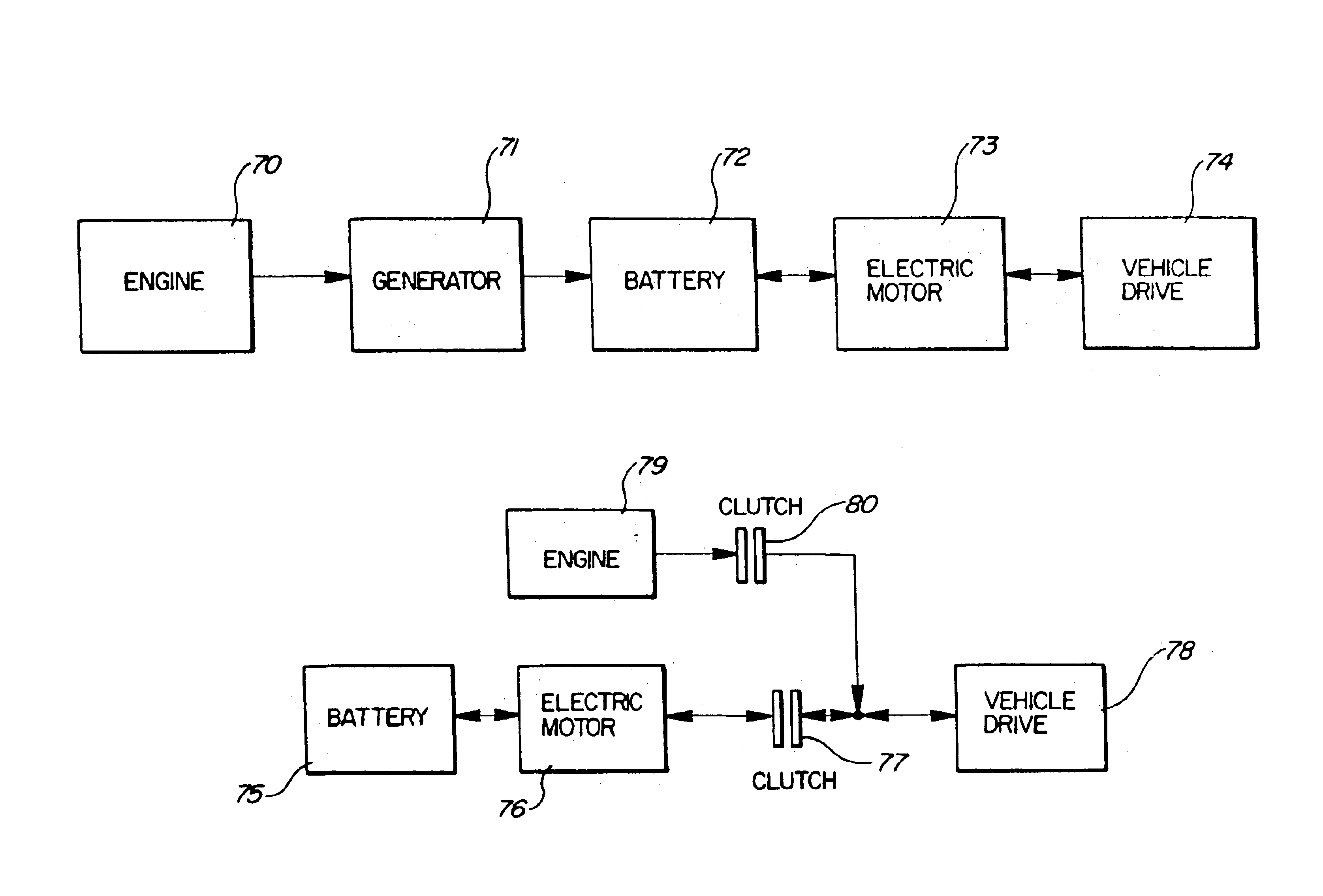
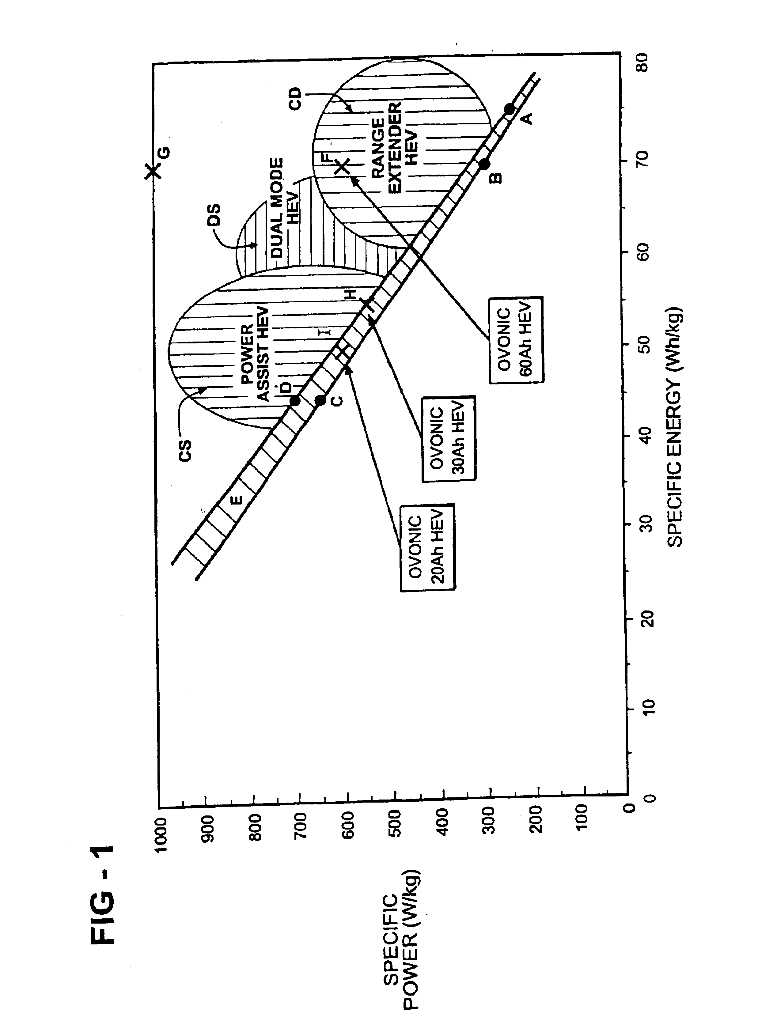
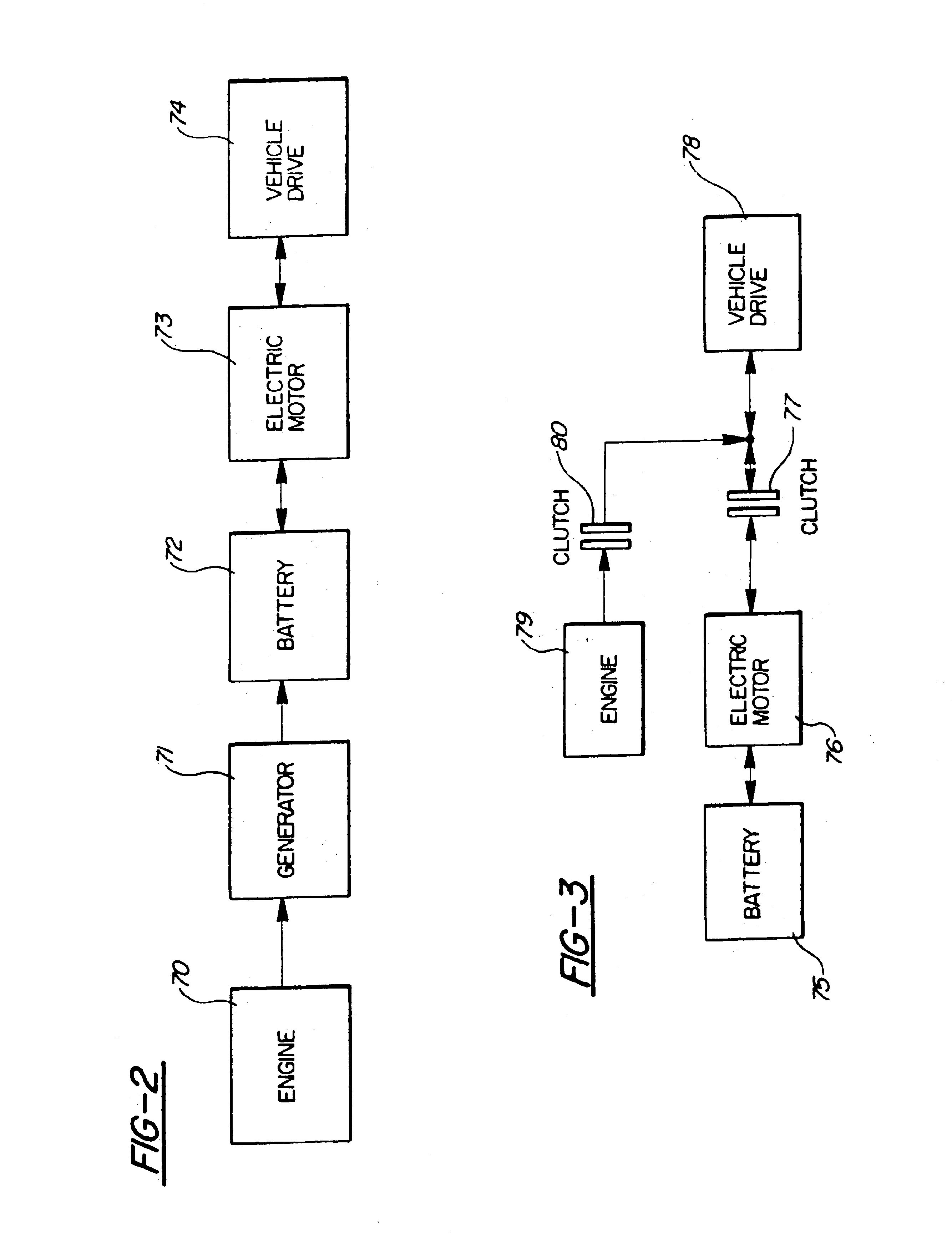
A hybrid electric vehicle drive system comprising a combustion engine, an electric motor and at least one nickel metal hydride battery module forming a power source for providing electric power to the electric motor, the at least one nickel metal battery module having a peak power density in relation to energy density as defined by:P>1,375−15Ewhere P is the peak power density as measured in Watts / kilogram and E is the energy density as measured in Watt-hours / kilogram.

Description

FIELD OF THE INVENTIONThe present invention relates generally to a hybrid electric vehicle incorporating an integrated propulsion system. More specifically, this integrated propulsion system comprises a combustion engine, an electric motor, high specific power, high energy density nickel-metal hydride (NiMH) batteries, and preferably a regenerative braking system. The NiMH batteries of the invention have negative electrodes with substrates of enhance current collecting capabilities, positive electrodes having enhance conductivity, and other improvements to enhance the power delivery capability of the battery and permit maximum operating efficiency during charge and discharge cycling while maintaining a combination of energy density and power density which provides enhanced performance beyond the capabilities of prior art NiMH battery systems.BACKGROUND OF THE INVENTIONAdvanced automotive battery development for vehicle propulsion has, in the past, been directed primarily at the requ...

Claims


Application Information

Patent Timeline
Patent Type & Authority Patents(United States)
IPC IPC(8): B60K6/04B60K6/00H01M2/10H01M10/42H01M4/70H01M4/80H01M10/34H01M4/24H01M4/38H01M4/66H01M10/50H01M2/26H01M4/62H01M10/44H01M2/16B60K6/24B60K6/28B60K6/46B60K6/48B60L50/64F02G1/00
CPCB60K6/24B60K6/46B60K6/48B60L11/126B60L11/1879F02G1/00H01M2/1072H01M2/1083H01M2/1653H01M2/26H01M4/24H01M4/242H01M4/383H01M4/626H01M4/661H01M4/667H01M4/80H01M4/801H01M4/803H01M4/805H01M10/345H01M10/5004H01M10/5006H01M10/5008H01M10/5016H01M10/502H01M10/5024H01M10/5032H01M10/5036H01M10/5038H01M10/5042H01M10/5053H01M10/5055H01M10/5059H01M10/5067H01M10/5075H01M10/5087B60K6/28Y02T10/705B60K2001/005H01M4/625H01M4/808H01M10/44H01M10/504H01M10/5073Y02E60/124Y02T10/6217Y02T10/6221Y02T10/6269Y02T10/6295Y02T10/7005Y02T10/7077Y10S903/907H01M10/625H01M10/63H01M10/615H01M10/653H01M10/6563H01M10/647H01M10/654H01M10/652H01M10/6557H01M10/6567H01M10/6555H01M10/6554H01M10/635H01M10/617H01M10/6566H01M10/651H01M10/613H01M10/658B60L50/62B60L50/64Y02E60/10Y02T10/62Y02T10/70H01M50/249H01M50/224H01M50/534H01M50/536H01M50/423H01M50/213Y02T10/7072
Inventor OVSHINSKY, STANFORD R.STEMPEL, ROBERT C.
Owner CHEVRON TEXACO TECH VENTURES
Learn More