Electron tube with a ring-less getter

a technology of ringless getters and electric tubes, which is applied in the manufacture of electric discharge tubes/lamps, tubes with screens, vacuum obtaining/maintenance, etc., can solve the problems of increasing the fabrication cost of the vessel, limiting the accommodating place of the vessel, and reducing the installation space. , the effect of simple handling and mounting

Inactive Publication Date: 2005-01-04
FUTABA CORPORATION
View PDF15 Cites 19 Cited by
  • Summary
  • Abstract
  • Description
  • Claims
  • Application Information

AI Technical Summary

Benefits of technology

It is, therefore, a primary object of the present invention to provide an electron tube capable of reducing installation space thereof, realizing simple handling and mounting thereof in any installation space, and a method for manufacturing the electron tube, the method activating a getter by irradiating a light on the getter.

Problems solved by technology

Accordingly, fabrication cost of the vessel increases.
The attachment of the vessel to the substrate is not technically easy.
There is a limitation in an accommodating place of the vessel, e.g., the substrate in FIG.
Further, since a considerable space is necessary for attachment of the vessel, a dead space increases, the dead space being a space which is not useful in a display function thereof.
As a result, the size thereof becomes large and the structure thereof becomes complex; and the handling and attachment thereof become difficult.
Especially, the handling or attachment of a thin fluorescent display device, e.g., having a space between two facing substrates smaller than 1.4 mm becomes difficult.
Since the fabrication cost of the vessel of a particular shape is high and the handling burden thereof is considerable, the manufacturing cost of the fluorescent display device becomes expensive.
Further, spaces for the vessel of a ring shape and a getter attachment member become large, thereby entailing limitations in providing slim and small fluorescent display device.
Further, since the getter material to be filled in the recessed portion is powder, handling thereof is not easy and the filling procedure thereof is burdensome.
Accordingly, it is difficult to fill the recessed portion with the getter material in an amount required to form the getter film.
In the conventional fluorescent display device as shown in FIG. 21B, an expensive deposition unit is necessary for forming the getter material layer 84; and in forming the getter material, the patterning thereof is difficult.
Since the getter material layer 84 formed by employing a deposition technique is thin, the glass substrate may be locally over-heated depending on a radiation time duration of a laser beam irradiated thereon, thereby entailing a development of a crack in the substrate; and it is difficult to form the getter material layer in an amount required to form a getter film.
However, when employing the paste coating technique, an expensive paste coating unit is needed; the pattering procedure in forming the getter material layer is difficult; and it is difficult to form the getter material layer on a component other than the substrate.
Further, in this case, a mixture other than the getter material in the paste may be evaporated to thereby produce unnecessary gas.
For example, in manufacturing a fluorescent display device, e.g., made of an acryl, even if the paste is formed by employing a solvent such as one which is thermally decomposed in sealing and exhaust procedures, the adhesion force of the getter material is not sufficient.

Method used


Image

  • Electron tube with a ring-less getter
  • Electron tube with a ring-less getter
  • Electron tube with a ring-less getter

Examples


first embodiment

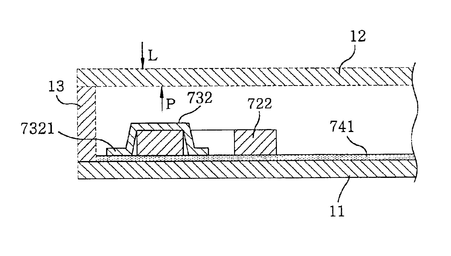
FIG. 16 describes the structure of the getter material layer shown in FIG. 15 in accordance with the present invention, providing an enlarged view of a part of FIG. 15B.

The ring-less getter 822 is bonded to the aluminum layer 842 formed on the anode substrate 21 by using the ultrasonic bonding technique. The ring-less getter 822 is formed by press-molding the powder of getter material and aluminum. At this time, it is preferable that the aluminum particles and the getter material particles are concentrated at lower parts 8223 and upper parts 8221 of the getter 822, respectively, though it frequently happens that the two types of particles are mixed with each other around middle parts 8222 of the getter 822. Herein, the upper, the middle and the lower parts of the getter 822 are mutually defined according to the relative distance from the aluminum layer 842, the parts being in contact with the aluminum layer 842 referred to as the lower parts of the getter 822. The getter in FIG. 16 ...

second embodiment

Referring to FIGS. 17A and 17B, there are respectively provided a plan view and a cross-sectional view of a fluorescent display device having a ring-less getter employing an ultrasonic bonding technique in accordance with the present invention. FIG. 17A is a partial plan view of an anode substrate having a ring-less getter installed thereon and FIG. 17B depicts a cross-sectional view taken along a line X3—X3 of FIG. 17A.

The ring-less getter shown in FIG. 17 includes a getter material layer 823 and an aluminum wire 833. The ring-less getter is formed by filling a press mold with powder of the getter material, installing the aluminum wire at the middle of the getter material powder and then performing the press molding process. The ring-less getter is installed on an aluminum layer 843 formed on an anode substrate 31 by bonding an end portion 8331 of the aluminum wire 833 to the aluminum layer 843 by using the ultrasonic bonding technique.

Since it is only required to ultrasonic-bondin...

third embodiment

FIGS. 18A and 18B respectively provide a plan view and a cross sectional view of a fluorescent display device having a ring-less getter employing an ultrasonic bonding technique in accordance with the present invention. FIG. 18A shows a plan view of an anode substrate having the ring-less getter installed thereon and FIG. 18B offers a cross-sectional view of part X4—X4 of FIG. 18A.

The ring-less getter in FIG. 18 includes a getter material layer 824 and an aluminum layer 834 and is formed by filling a press mold with the powder of getter material and aluminum and then by performing a press molding process. The ring-less getter is installed on an aluminum layer 844 formed on an anode substrate 41 by fixing the aluminum layer 834 to the aluminum layer 844 by using the ultrasonic bonding technique. Herein, it is not required to weld the whole surface of the aluminum layer 834 but just needed to weld two or three places thereon.

When a laser beam is radiated to the getter material layer 8...


PUM


Abstract

In a method for manufacturing an electron tube including a front substrate and a back substrate, a wiring and an electrode are formed on the front substrate and / or the back substrate. A component is mounted on the front substrate and / or the back substrate. A ring-less getter is mounted on at least one of the front substrate, the back substrate and the component. A vessel is assembled and sealed so that the front substrate faces the back substrate. A light is irradiated on the ring-less getter from outside of the sealed vessel, thereby activating the ring-less getter.

Description

FIELD OF THE INVENTIONThe present invention relates to an electron tube and a method for manufacturing the same; and, more particularly, to a fluorescent display device having a getter and a method for manufacturing the same.BACKGROUND OF THE INVENTIONReferring to FIGS. 20 and 21, structure and function of a conventional fluorescent display device having a getter will be described. FIGS. 20 and 21 show cross sectional views of the conventional fluorescent display device, respectively. In FIGS. 20A and 20B, reference numerals 70, 71 and 72 represent a side substrate, a first substrate and a second substrate, respectively, which constitute a vacuum vessel of a fluorescent display device.Referring to FIG. 20A, a supporting member 74 is fixed to an insulation layer 73 formed on the second substrate 72, wherein a metal vessel 75 having getter material 76 filled therein is attached to the supporting member 74. When a laser beam is irradiated from outside of the second substrate 72 onto a ...

Claims


Application Information

Patent Timeline
Patent Type & Authority Patents(United States)
IPC IPC(8): H01J29/94H01J29/00H01J9/385H01J9/38H01J31/15
CPCH01J9/385H01J29/94H01J2209/385H01J31/15
Inventor YONEZAWA, YOSHIHISAOGAWA, YUKIOISHIGE, SHOGO
Owner FUTABA CORPORATION
Why Eureka
Try Eureka