Active common mode EMI filters

a filter circuit and common mode technology, applied in the direction of dc circuit to reduce harmonics/ripples, pulse manipulation, pulse technique, etc., can solve the problems of reducing affecting the efficiency of emi filter circuits, and creating unnecessary noise currents and harmonics on ac lines, etc., to achieve more effective filtering action, reduce common mode noise, and reduce bias power supply voltage

Inactive Publication Date: 2005-01-11
INFINEON TECH AMERICAS CORP
View PDF5 Cites 20 Cited by
  • Summary
  • Abstract
  • Description
  • Claims
  • Application Information

AI Technical Summary

Benefits of technology

A third aspect of the invention relates to a new method of generating bias power supply for the active EMI filter circuits shown in FIGS. 1A and 1B. The floating power supply can be derived from the common mode noise, which the active EMI filter is intended to cancel, utilizing the same current transformer. In one embodiment, no additional winding is required. Since the power source of the bias floating power supply is the common mode noise, the power supply voltage is approximately proportional to noise amplitude. As the noise increases, the bias power supply voltage increases, resulting in more effective filtering action. This effectively reduces common mode noise, therefore reducing bias power supply voltage in response to the lower noise canceling action that is required. Therefore the overall circuit provides a closed loop action between canceling noise and noise generated power supply.

Problems solved by technology

This would create unnecessary noise currents and harmonics on the AC lines.
This results in possible oscillation of the system and furthermore requires a current transformer of moderate size.
A problem with MOSFETs or IGBTs, however, is that the gate to source drive voltage needed to deliver the required output current is relatively high.
Unfortunately, the higher the voltage across the primary, the greater the magnetizing component of the primary current.
The greater the error between the output current of the active filter and the primary common mode current, the poorer the performance of the active filter.
A significant error exists between iOUT and ICOMDRIVE.
The disadvantage is that a multiple turn hand-wound primary is now needed.
A multiple turn primary of large diameter wire has to be hand-wound onto the toroid, and this is expensive.
Unfortunately, a single-turn current-sensing transformer requires a magnetic core with an inconveniently large cross-section.
The magnetizing component of common mode current in the primary is not transmitted to the secondary, thus it becomes an “error” in the output current iOUT of the amplifier.
This degrades the performance of the active filter.
A problem with this type of current mirror is that it has inaccuracies due to tolerances in the matching of impedances and / or transistor characteristics.

Method used


Image

  • Active common mode EMI filters
  • Active common mode EMI filters
  • Active common mode EMI filters

Examples


first embodiment

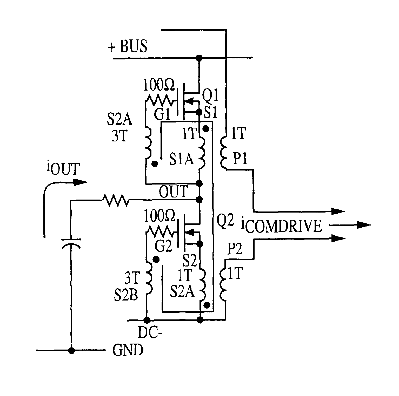
The proposed solution that allows a single turn primary is illustrated in FIG. 4(a). The primary windings P1 and P2 (of “large” diameter wire) and secondary windings S1A and S2A (of “small” diameter wire), each have one turn, thus fulfilling the requirement for just a single turn primary. “Overwindings” S1B and S2B, also of “small” diameter wire, are added, to boost the voltage applied between gate and source of the MOSFET, relative to the primary voltage.

Since the required gate-source drive voltage for a given primary current is fixed by the characteristics of the MOSFET, the voltage across each primary winding is now reduced in the ratio of 11+N,

where N is the number of “overwind” turns on S1B and S2B relative to the number of primary turns. Thus, the magnetizing current error is reduced in the same ratio.

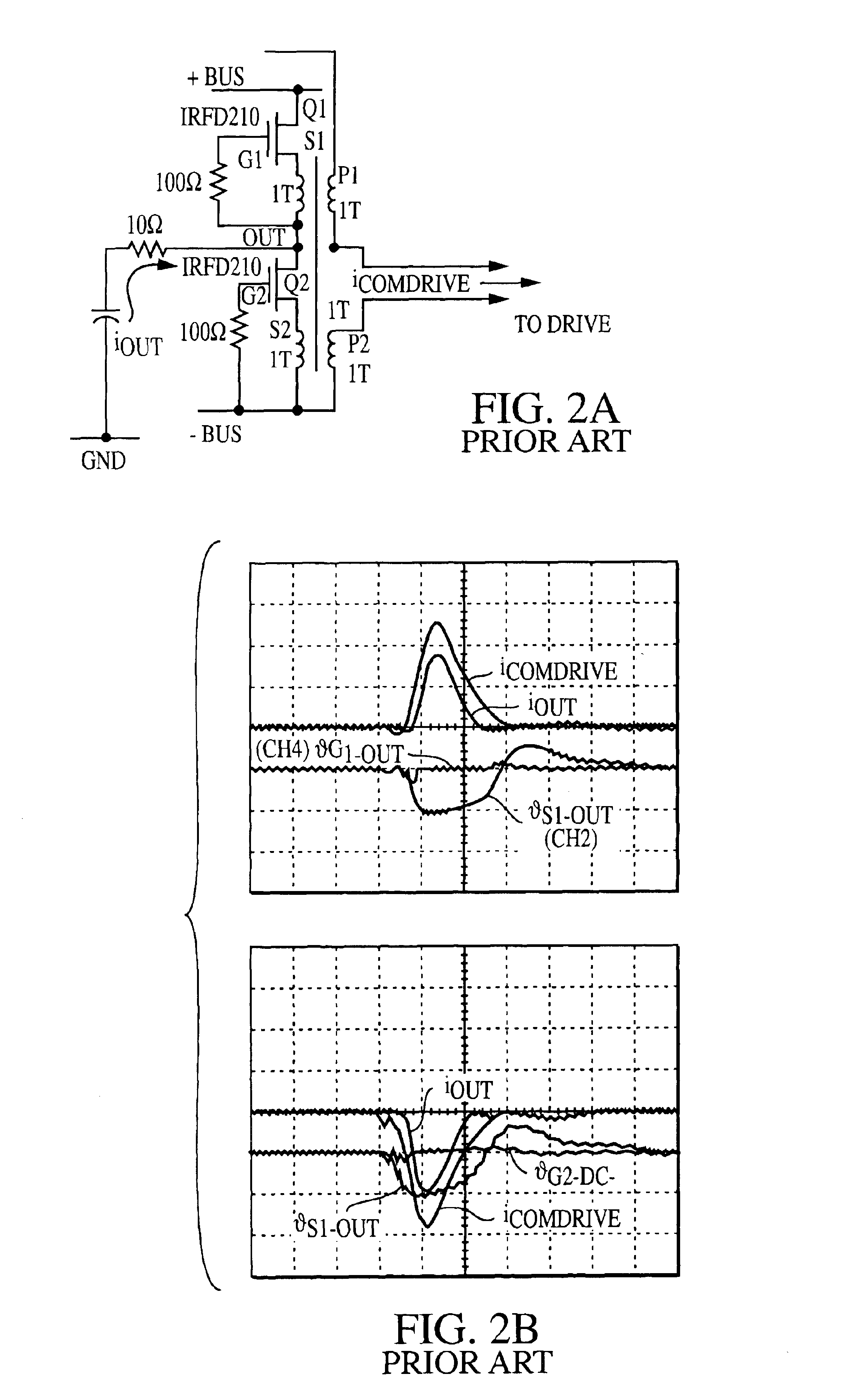
FIG. 4(b) shows waveforms of iCOMDRIVE and iOUT, with one primary turn and N=3. The error between iOUT and iCOMDRIVE has been significantly reduced, as compared with the waveform...

second embodiment

The second embodiment is illustrated by the example in FIG. 5. Here, there are 10 secondary turns on the 1-turn primary sensing transformer, CT1. The relative magnetizing current error is thus {fraction (1 / 10)} of what it would be with just a single secondary turn on the same core. The current that flows in the secondary SA, and in the 100-turn primary winding of a second small current transformer CT2, is thus a relatively accurate replica of the primary current, but with amplitude of one tenth of the primary current. CT2 carries only “common mode” current, therefore it has small wire size for both primary and secondary windings.

CT2 has 10 secondary turns. Thus, the secondary current of CT2 is 10× the primary current, and the current gain of the overall circuit from iCOMDRIVE to iOUT has the desired value of unity.

The voltage reflected to the primary of CT2 is 10× the base-emitter voltage of Q1 / Q2 i.e. about 10V. Assuming CT2 has the same cross section as CT1 (but not necessarily as...

third embodiment

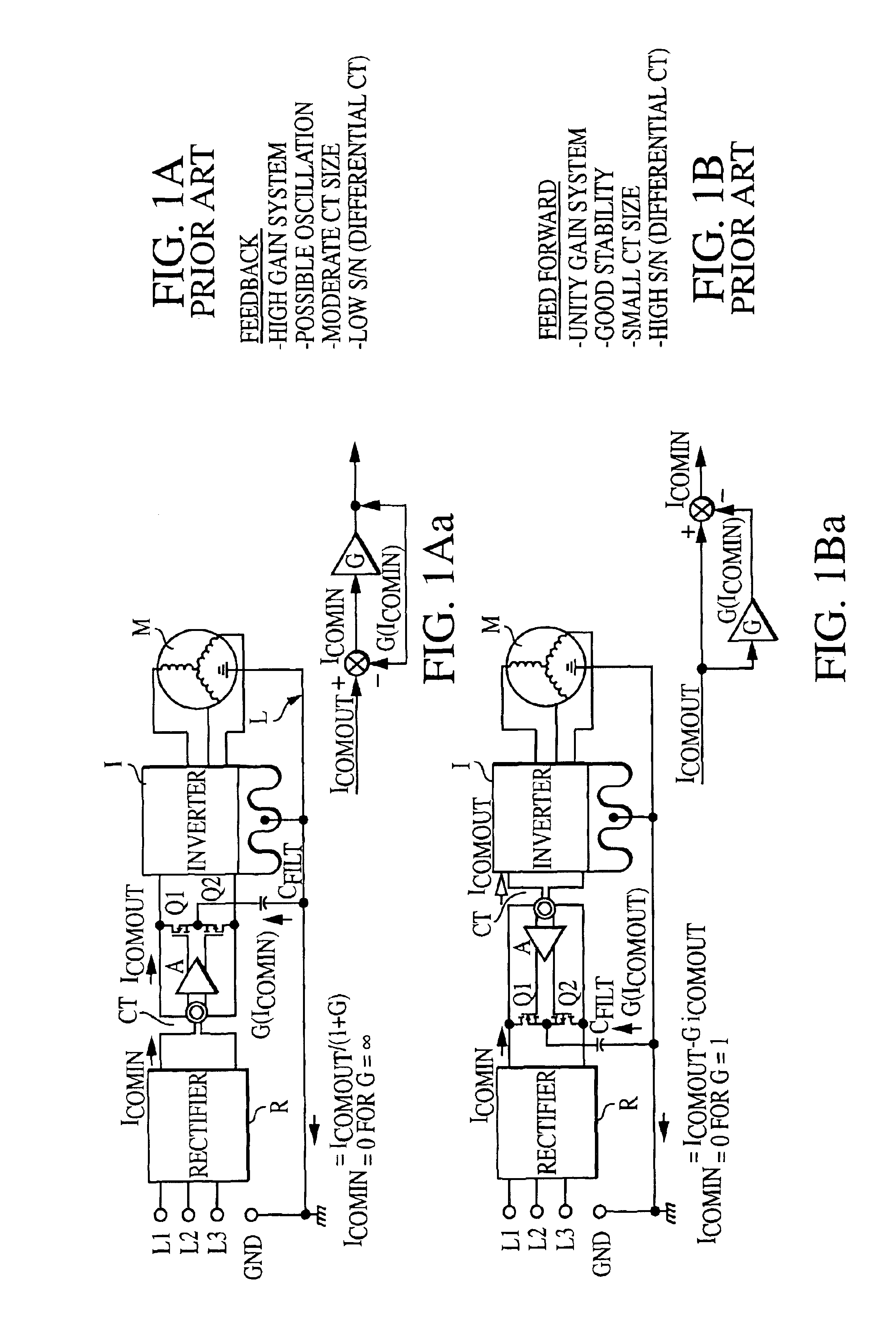
FIG. 6 is a basic diagram of a noise powered noise canceling active EMI filter. The active filter method is based on the feedforward noise canceling method of FIG. 1B. FIG. 7 is a basic diagram of a noise powered noise canceling filter based on the feedback noise canceling method of 1A. The floating bias power supply provides bias voltage to the active EMI filter amplifier in either the feedback or the feedforward circuit. The embodiments of FIGS. 6 and 7 each include a CT which has a winding for noise sensing that is separate from the winding for the floating power supply.

In FIGS. 6 and 7 the noise powered active EMI filter is applied to AC motor inverter system. In both cases, the AC line is three phase input (L1, L2, L3) along with ground terminal, GND. It can be a single phase AC line as well. In general, the noise powered active EMI filter can be applied to any system which contains power switching device(s) and / or forms a power inverter such as a switch mode power supply, unin...


PUM


Abstract

An active EMI filter for reducing common mode noise current in a circuits, comprising: a transistor stage having two transistors coupled in series, a current sensor for sensing the common mode noise current, the current sensor having an output driving the transistor stage, whereby each of the transistors is driven in response to the common mode noise current, a capacitor coupling the transistor stage and the ground return line, the capacitor providing a cancellation current to cancel the common mode noise current, the current sensor comprising a current transformer having a primary coupled with the circuit having the common mode noise. The current sensor and the transistor stage may be coupled in a feed forward arrangement wherein the transistor stage and the current sensor have an amplitude gain of approximately unity; or in a feedback arrangement wherein the transistor stage and current sensor provide high gain.

Description

BACKGROUND OF THE INVENTION1. Field of the InventionThe invention relates to active common mode EMI filter circuits using bipolar transistors or MOSFETs in combination with common mode current sensing transformers.2. Background ArtVarious circuits of this type, having a unity gain amplifier in a feedforward configuration, or a high-gain amplifier in a feedback configuration, have previously been disclosed.Active EMI filters are known and are described, for example, in co-pending applications Ser. No. 09 / 816,590, filed Mar. 23, 2001 entitled ACTIVE FILTER FOR REDUCTION OF COMMON MODE CURRENT (IR-1744), and Ser. No. 10 / 336,157, filed Jan. 2, 2003, entitled ACTIVE EMI FILTER WITH FEED FORWARD CANCELLATION (IR-2146), the disclosures of which are incorporated herein by reference.Active EMI filter circuits may use the feed forward design as disclosed in the above noted application Ser. No. 09 / 816,590. See FIGS. 1A and 1B. The feed forward design, shown in FIG. 1B, has fundamentally superi...

Claims


Application Information

Patent Timeline
Patent Type & Authority Patents(United States)
IPC IPC(8): H02M1/12H02M1/14H02M1/15H02M1/44H02M5/458H03H11/04
CPCH02M1/12H02M1/14H02M1/44H02M5/458H02M1/15H02M2001/123H02M1/123
Inventor TAKAHASHI, TOSHIOPELLY, BRIAN
Owner INFINEON TECH AMERICAS CORP
Why Eureka
Try Eureka