Electrosurgical system

a surgical system and electrosurgical technology, applied in the field of electrosurgical instruments, can solve the problems of increasing the risk of forceps jaws being stuck to the tissue, damage to untreated areas of the vessel, and excessive spread of coagulation to adjacent tissues, so as to reduce the lateral margin of thermal effect, and reduce the risk of tissue sticking

Inactive Publication Date: 2005-01-18
GYRUS MEDICAL LTD
View PDF27 Cites 1583 Cited by
  • Summary
  • Abstract
  • Description
  • Claims
  • Application Information

AI Technical Summary

Benefits of technology

Once vapour is formed, the highest current densities occur around the edges of the vapour bubbles, causing further heating and expansion of the vapour bubble until the end of the respect pulse burst, as expansion of the bubbles being such that the areas of highest current density are forced into untreated regions of tissue below the tissue surfaces. This reduces the risk of localised heating of the forceps jaws and hence reduces the risk of tissue sticking.
These effects result in preferential and more uniform distribution of energy dissipation within the target tissue to provide a method of treating tissue whereby a lateral margin of thermal effect is reduced and fu

Problems solved by technology

The most significant problems encountered, when using conventional bipolar r.f. electrosurgery, are related to the distribution of energy throughout the tissue grasped between the forceps.
This leads to an excessive spread of the coagulation to adjacent tissues, and increases the risk of the forceps jaws becoming stuck to the tissue.
This sticking can be sufficiently severe to cause coagulated tissue to be torn away when releasing the forceps, leading to damage of untreated areas of the vessel, and significant bleeding.
The low impedance matching capability of this type of generator is limited, with maximum current delivery typically being in the region of 1.5A at full power.
Despite these advances, none of the known bipolar r.f. generators overcomes the problems of differential energy absorption within the tissue due to the variation in tissue impedance, the geometry of the forceps jaws, the presence of conductive fluids and tissue compression.
As a result

Method used


Image

  • Electrosurgical system
  • Electrosurgical system
  • Electrosurgical system

Examples


Embodiment Construction

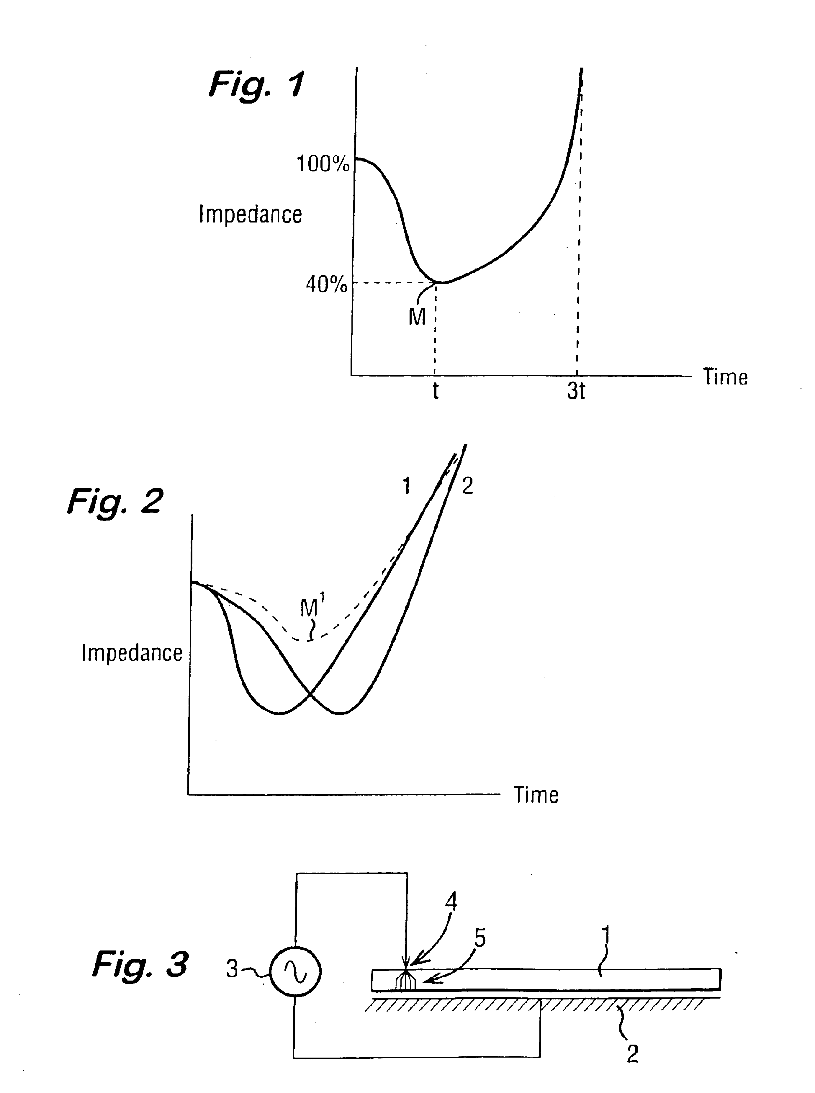
Referring to the drawings, FIG. 1 is a graph showing the ideal behaviour of tissue impedance against time during the application of bipolar r.f. energy. The impedance is seen to fall during the initial phase of application as a result of heating of electrolytes in the vicinity of the tissue being treated. A minimum M is reached, following which the impedance begins to rise as the tissue is desiccated and becomes less conductive. Treatment, in terms of coagulation of the tissue, optimally occurs around the point M of minimum impedance. Continued delivery of energy beyond this point M merely serves to increase the lateral margin, to increase the temperature of the application electrodes, typically a pair of forceps jaws, due to increased steam generation and to increase the risk of tissue sticking. Increased ion mobility can cause a 60% impedance reduction over a typical temperature change of 37° C. to 100° C. In practice, however, a 60% reduction is never seen since the tissue is nev...


PUM


Abstract

An electrosurgical system has an electrosurgical generator and a bipolar electrosurgical instrument, the generator being arranged to perform a treatment cycle in which radio frequency energy is delivered to the instrument as an amplitude-modulated radio frequency power signal in the form of a succession of pulses characterized by successive pulses of progressively increasing pulse width and progressively decreasing pulse amplitude. There are periods of at least 100 milliseconds between successive pulses, and the treatment cycle begins with a predetermined pulse mark-to-space ratio. Energy delivery between pulses is substantially zero. Each burst is of sufficiently high power to form vapor bubbles within tissue being treated and the time between successive pulses is sufficiently long to permit condensation of the vapor.

Description

FIELD OF THE INVENTIONThis invention relates to an electrosurgical instrument, to an electrosurgical method and to an electrosurgical system. More specifically, the present invention provides a bipolar radiofrequency (r.f.) electrosurgical output, the characteristics of which produce faster, more controlled and more effective sealing of vascular structures such as might be performed during endoscopic surgery, and the like.BACKGROUND OF THE INVENTIONThe use of r.f. current to effect the cutting and coagulation of body tissues has been known for many years, and comes under the broad description of electrosurgery. Two techniques to deliver the r.f. current to the tissues are in common usage today.The first of these, monopolar electrosurgery, involves the use of an active (tissue treatment) electrode and a remote return (or neutral) electrode (or pad) placed on an external surface of the patient's body. Current flows from the active electrode, through the target site, and through any ot...

Claims


Application Information

Patent Timeline
IPC IPC(8): A61B18/14
CPCA61B18/1445A61B18/1233A61B2018/00666A61B2018/00875A61B2018/00726A61B2018/00779A61B2018/00702
Inventor GOBLE, COLIN C. O.
Owner GYRUS MEDICAL LTD
Why Eureka
Try Eureka