
Mutual inductance bridge for detection of degradation in metallic components

a technology of inductance bridge and metal components, applied in the direction of electrical/magnetic thickness measurement, material magnetic variables, instruments, etc., can solve the problems of almost one-half of all coal fired power plant outages, major limiting factor of available generating capacity, and internal corrosion, so as to mitigate the effect of avoidable downtime incidents

Inactive Publication Date: 2005-01-18
AVISTAR
View PDF7 Cites 3 Cited by
  • Summary
  • Abstract
  • Description
  • Claims
  • Application Information

AI Technical Summary

Benefits of technology

"The patent text describes a method for detecting wall thinning in boiler tubes using a mutual inductance bridge circuit. The method is sensitive to changes in the tubing caused by external corrosion and internal defects such as sawtooth defects. The method can be used to reliably and rapidly assess tube thinning conditions, predicting future failure events and avoiding downtime incidents. The method does not require accurate measurement of the wall thickness and can be used with different types of boiler tubes. The mutual inductance bridge circuit is a sensitive and reliable technique for detecting wall thinning in boiler tubes, which is important for ensuring reliable electric production and avoiding costly boiler failures."

Problems solved by technology

Internal corrosion is caused by defective water chemistry combined with thermal cycling.
Unanticipated boiler failures, caused by the breakout of a thin wall, account for almost one half of all coal fired power plant outages.
Due to the importance reliable electric production, these outages represent a major limiting factor in the available generating capacity.
In the event that production falls short of demand, rolling blackouts become routine.
Analysis of boiler tube failures shows the repetitive nature of these events.
That is, following an economizer failure, several additional economizer failures are likely to occur in close proximity.
Several known defects can be present in economizers.
One of the most prevalent faults is called the sawtooth defect.
In this case, aerodynamic flow of gasses cause material to be eroded unevenly between the fins and only in a small area facing the direction of flow.
It results in a smaller amount of material removal than would be present with even wear and is exceptionally difficult to detect.
But, the absolute wall thinning in one small area can lead to tube failure.
This explains why detection is limited to significant defects rather than pinholes, cracks and weld problems.

Method used


Image

  • Mutual inductance bridge for detection of degradation in metallic components
  • Mutual inductance bridge for detection of degradation in metallic components
  • Mutual inductance bridge for detection of degradation in metallic components

Examples


Embodiment Construction

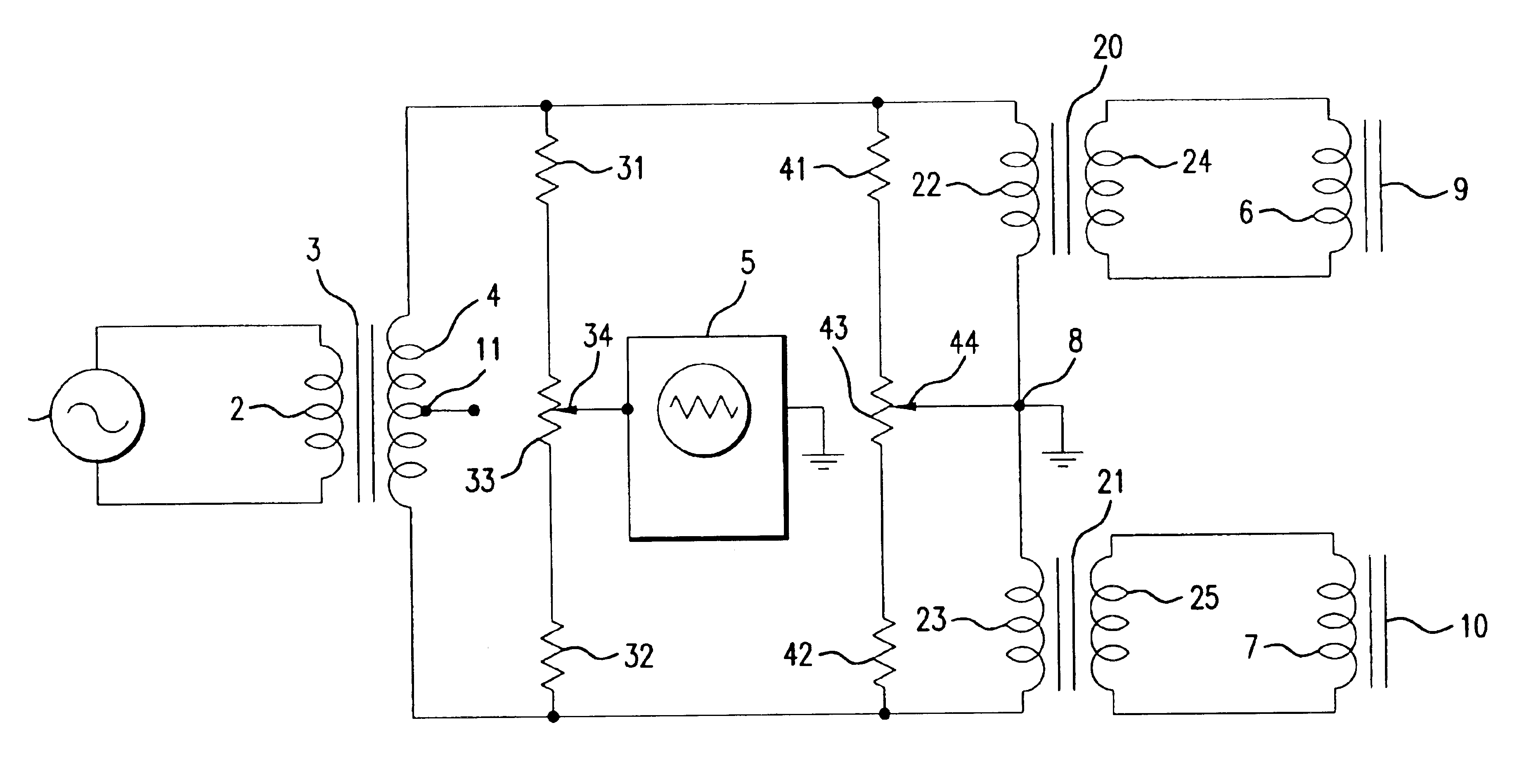
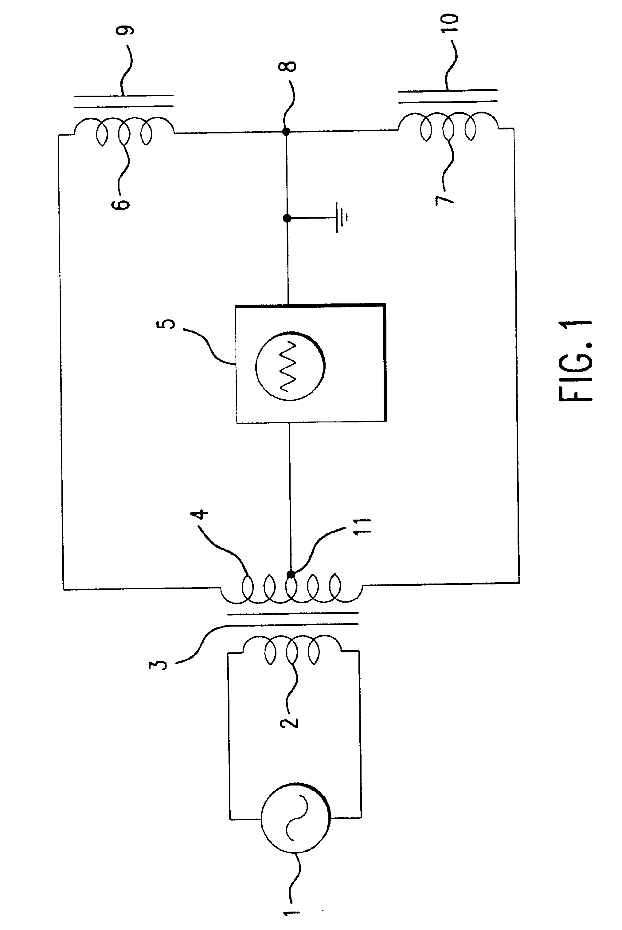
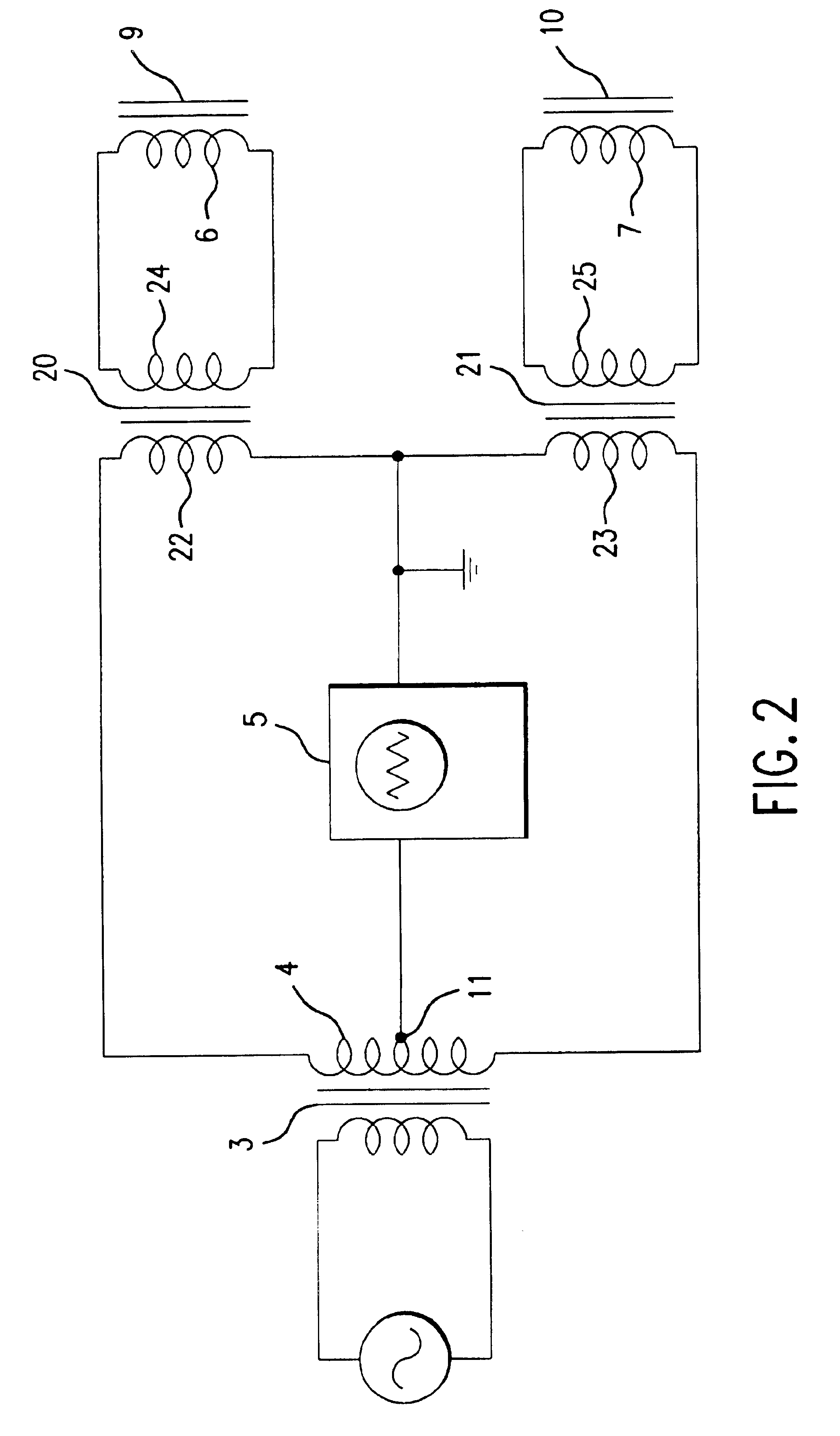
In FIG. 1 there is shown the simplest form of a Mutual Inductance Bridge defect detection system of this invention. In this embodiment, an alternating current source (1) applies a voltage to an input coil (2) of a first transformer (3). The secondary (4) of the first transformer (3) is center tapped. The center tap (11) of the transformer secondary (4) is connected to an oscilloscope (5) which measures the voltage between the center tap (4) of the transformer (3) and ground. The oscilloscope (5), therefore, detects imbalances in the bridge circuit only. One side of the transformer (3) secondary (4) is connected to a first test coil (6) and the other side of the secondary (4) is connected to a second test coil (7). Test coils (6) and (7) are connected together at point (8) which is in turn connected to ground. As shown in FIG. 1, adjacent to each of test coils (6) and (7) are metallic portions (9) and (10). If the metallic portions (9) and (10) are absent, and if the first and second...


PUM

PropertyMeasurementUnit
thicknessaaaaaaaaaa
inductanceaaaaaaaaaa
alternating voltageaaaaaaaaaa

Abstract

An inductive bridge circuit using mutual inductances to transform impedances is used for detection of wall-thinning defects in metals. The bridge circuit has a first test coil placed adjacent to a good metal section and a second test coil placed adjacent to a metal to be tested. The bridge circuit compares the inductance in the first coil and inductance in the second test coil to compare wall thinning defects. The apparatus may also include first and second measuring transformers which are connected between the bridge circuit and the test coils where the transformers provide for impedance matching and reduced current requirements in the bridge. The circuit may also include one or more potentiometer circuits connected across the bridge which are used for compensating for imbalance of impedance between the first and second test coils when the coils both have known good metal sections adjacent to them.

Description

BACKGROUND OF THE INVENTION(1) Field of the InventionThis invention relates to nondestructive testing for defects in metals and more particularly, for defects in boiler tubes or water walls used in the electric utility industry. More particularly, this invention is used for detection of erosion which occurs as a result of abrasive particles contained in coal feedstock. The erosion may be both internal and external. This invention provides a nondestructive inductance-based test technique that reliably assesses tube or wall thinning conditions and, thus, enables the prediction of future failure events.(2) Description of Related ArtIn the prior art, nondestructive techniques for measuring boiler tube erosion or water wall erosion comprise eddy-current testing, dye-penetrant testing, ultrasound testing, and x-ray testing. These systems are not cost effective because they are extremely slow, require use of delicate instruments which are incapable of survival in an industrial setting, req...

Claims


Application Information

Patent Timeline
Patent Type & Authority Patents(United States)
IPC IPC(8): G01N27/90G01N27/82
CPCG01N27/9046G01N27/82
Inventor MIGLIORI, ALBERTRHODES, GEORGE W
Owner AVISTAR
Learn More