
Sintered bearing and production method therefor

a technology of bearings and friction, applied in the direction of sliding contact bearings, mechanical equipment, rotary machine parts, etc., can solve the problems of difficult use of bearings in portions that are usually cleaned, complicated structures, and unsuitable lubricating oil impregnated bearings, etc., to achieve stable dynamic pressure properties, prevent leakage, and prevent wear

Inactive Publication Date: 2005-01-25
MINEBEA CO LTD +1
View PDF7 Cites 11 Cited by
  • Summary
  • Abstract
  • Description
  • Claims
  • Application Information

AI Technical Summary

Benefits of technology

Therefore, an object of the present invention is to provide a sintered bearing and production method therefor capable of facilitating controlling and ensuring uniformity of the coating thickness, and capable of forming an extremely thin coating while obtaining high securing strength of the resin coating.
The sintered bearing produced by the invention is thus coated by the resin coating over the entire surface thereof, and is therefore capable of avoiding release of noxious gases and penetration of water, and is capable of maintaining corrosion resistance since it is not exposed to air. Typical sintered bearings lubricate with lubricating oil retained in the pores. In contrast, the bearing in the invention has lubrication by the resin coating formed by the electrodeposition instead of the lubricate, whereby fitting performance between the bearing and a rotating shaft, wear resistance, corrosion resistance, and cleanliness can be obtained.
In the invention, thickness of the resin coating can be easily controlled and made uniform since the electrodeposition is applied. The thickness of the resin coating is easily controlled by controlling the voltage applied in the electrodeposition, application time, temperature of the electrolyte, and the like. The thickness of the resin coating is uniform according to the characteristics of the electrodeposition, and bearings having suitable coating thickness according to the equipment employed are therefore produced. Furthermore, the coating thickness can be extremely thin, so that dimensional stability originally provided in sintered bearings is maintained, and the bearings can be applied to small parts, and additionally, the method can easily applied to mass-production.
In the production method of the invention, the raw metallic material powder is mixed with a magnetic powder, and a resultant bearing from the sintered compact is magnetized after the electrodeposition. Overall, the bearing produced in this manner is employed as a magnet since the magnetic powder is magnetized. When a magnetic fluid is used as a fluid, the magnetic fluid is usually held between the sintered bearing and a rotating shaft by the magnetic force of the bearing, and stable dynamic pressure properties are therefore obtained and leakage thereof is restrained.
In bearings including a magnetic powder, fitting performance with a rotating shaft is not sufficient and wear may easily occur since comparatively hard magnetic powder is exposed on the surface of the bearing. The magnetic powder exposed on the surface may be broken or scattered by abrasion, and the loosened particles function as an abrasive between the rotating shaft and the bearing. As a result, wear is promoted and vibration characteristics are not stable, and accurate rotation is not obtained. In contrast, the bearing produced by the production method of the invention is formed with the resin coating over the entire surface thereof, whereby the resin coating lubricates the bearing surface, and the fitting performance with the rotating shaft is improved in spite of dispersion of the magnetic powder. Furthermore, the resin coating restrains breakage and scattering of the magnetic powder. As a result, wear due to the magnetic powder existing between the inner peripheral surface of the bearing and the rotating shaft is restrained, and vibration performance is therefore stable, and highly accurate rotation is obtained.
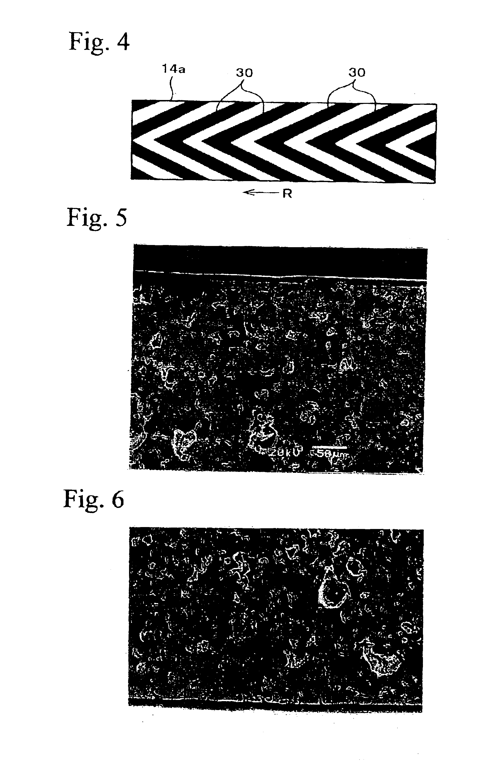
In the production method of the invention, grooves for generating dynamic pressure may be formed on an inner peripheral of the bearing. The grooves may be formed, for example, in a sizing process in which the bearing hole is finished to the predetermined dimension. In this production method, the bearing surface is covered by the resin coating and the pores on the surface are sealed, whereby the dynamic pressure generated by the fluid supplied into the grooves does not penetrate, and highly accurate rotation and high stiffness are ensured. Furthermore, the entire surface of the bearing is covered by the resin coating, so that noxious gases are not generated from the inside of the bearing if the temperature of the bearing increases. Therefore, gas generated from pores, which has been a concern on conventional bearings, is avoided. In addition, in the bearing in which a magnetic powder is mixed therein, breakage and scattering of the magnetic powder are avoided in forming the grooves for generating dynamic pressure, and the grooves can be easily worked and the shape of the grooves and dimensional accuracy of the inner peripheral surface of the bearing are improved.

Problems solved by technology

The lubricating oil impregnated bearings are not suitable for some kinds of products.
That is the lubricating oil retaining sintered bearings sometimes exude the oil and contaminate the surroundings, and the bearings are not easy to use in portions required to usually be cleaned, such as hinges of covers in notebook-type personal computers and mobile telephones.
However, the waterproof means require complicated structures, and maintenance is not easy since the case must be opened when the lubricant must be resupplied.
However, dry-type sintered bearings are corroded in high temperature and high moisture environments.
Corrosion in the dry-type sintered bearing results in shortening of the service life in addition to wear and noise, and means for improving corrosion resistance have therefore been required.
Thus, conventional sintered bearings involve various problems such as leakage of lubricating oil, complicated structure for waterproof means, generating noxious gases, and poor corrosion resistance.
However, such as the inner peripheral surface of the bearings are required to have high dimensional accuracy, and the above resin coating coverage is not suitable for accurate dimensions.
That is, there are several difficulties in the resin coating process, in controlling and ensuring uniformity of coating thickness, such as these difficulties that resin coating cannot be formed in complicated bearing shape, and an extremely thin resin coating cannot be formed.
Therefore, dimensional stability which is an advantage of sintered bearings, is deteriorated, in particular, the bearings are not suitable for small parts.
Furthermore, the resin is difficult to enter into the small pores on the surface of the bearing, and the securing strength of the resin is low and the resin coating is stripped easily.

Method used


Image

  • Sintered bearing and production method therefor
  • Sintered bearing and production method therefor
  • Sintered bearing and production method therefor

Examples


Embodiment Construction

An embodiment of the invention will be explained with reference to the drawings hereinafter.

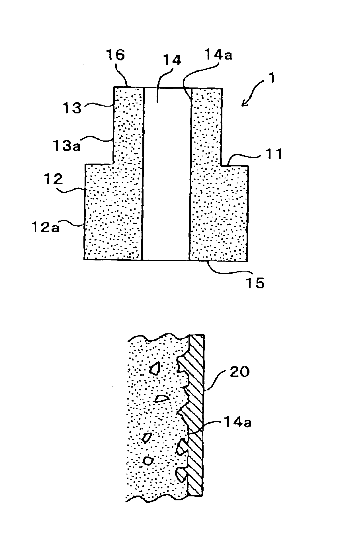
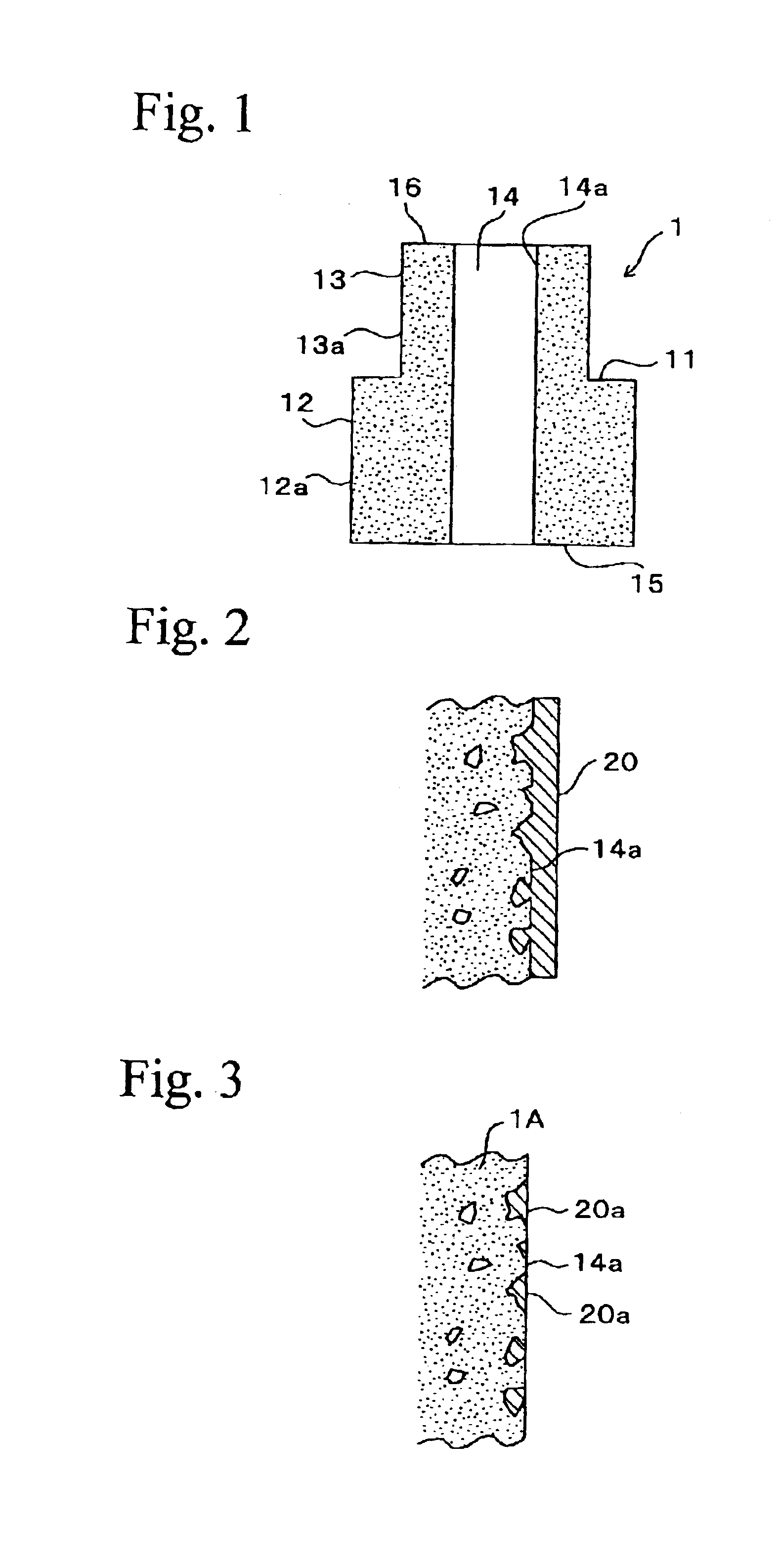
FIG. 1 shows a cylindrical sintered bearing produced by the production method of the invention. The sintered bearing 1 is formed with an annular stepped portion 11 consisting of a planar surface along the radial direction, and the stepped portion 11 divides the outer surface of the bearing 1 into a large diameter portion 12 and a small diameter portion 13. The bearing 1 has a bearing hole 14 at its center, into which a rotating shaft (not shown) is inserted, has a uniform diameter, and the inner surface of the bearing hole 14 is employed as a bearing surface. The entire surface of the bearing 1, that is, the outer peripheral surfaces 12a and 13a of the large diameter portion 12 and the small diameter portion 13, bearing surface 14a, and end surfaces 15 and 16 of the large and small diameter portions 12 and 13, and end surface of the stepped portion 11, are covered by a resin coating 20 having...


PUM

PropertyMeasurementUnit
thicknessaaaaaaaaaa
thicknessaaaaaaaaaa
thicknessaaaaaaaaaa

Abstract

A production method for a sintered bearing, comprises compacting a raw metallic material powder into a bearing green compact; sintering the green compact into a sintered compact; and forming a resin coating over the entire surface of the sintered compact by electrodeposition.

Description

BACKGROUND OF THE INVENTION1. Field of the InventionThe present invention relates to sintered bearings and production methods therefor used in sustaining various rotational products and bearings for motors, for example, information devices, office equipment, electrical appliances, construction equipment, and the like.2. Related ArtSintered bearings produced according to a powdered metal sintering technique have been widely used for the above applications since they are easy and inexpensive to mass-produce, and in particular, because of their dimensional stability. Sintered bearings are roughly produced by compacting a metallic raw metallic powder into a bearing green compact, sintering the green compact into a sintered compact, then subjecting the sintered compact to a sizing process to finish into predetermined dimensions and shape.Sintered bearings are commonly used as oil retaining sintered bearing in which lubricating oil is impregnated in pores therein for lubrication and dynam...

Claims


Application Information

Patent Timeline
Patent Type & Authority Patents(United States)
IPC IPC(8): F16C33/04F16C33/12F16C33/10F16C33/20F16C17/02
CPCF16C17/026F16C33/107F16C33/12F16C33/201F16C33/14Y10T29/49639Y10S384/902F16C2204/60F16C2220/20F16C2223/70F16C2223/04
Inventor YOSHIMURA, NORIYUKIHIROSE, JUNNII, KATSUTOSHI
Owner MINEBEA CO LTD
Learn More