Data transmission

a data transmission and data technology, applied in the field of data transmission, can solve the problems of inability to meet the needs of large-scale installations, etc., and achieve the effect of high reliability

Inactive Publication Date: 2005-01-25
TRU TEST
View PDF4 Cites 5 Cited by
  • Summary
  • Abstract
  • Description
  • Claims
  • Application Information

AI Technical Summary

Benefits of technology

An object of the present invention is thus to provide a method and means of transmission of data along electric fences which will have a high level of reliability or at least is able to provide the public with a useful choice.
As the device according to the present invention transmits information in the form of very short, high power bursts, the energy required for each burst can be drawn from a capacitor contained within the transmitting device. The capacitor can be slowly recharged from a small, lightweight battery during the intervals between bursts. Thus according to the present invention a small, lightweight and low cost battery with a relatively high output impedance can be used whilst providing acceptable service life and achieving high frequency signals with an instantaneous electrical power of several watts.

Problems solved by technology

When touching the electric fence, the electric pulse is experienced as unpleasant or painful, forming an effective deterrent against crossing or applying pressure to the electric fence.
For various reasons, known remote control systems relying on transmission of data along an electric fence conductor have suffered from drawbacks.
For example, it has been suggested to use a low voltage DC signal to transmit along an electric fence, however, this method often performs very poorly on larger installations and on installations which receive limited servicing.
This poor performance is often due to excessive attenuation of the low voltage DC signal by poor or defective wire joints along the electric fence.
Because it is desirable that the transmitter can be made a battery powered portable device and thus be hand held by the user, there are practical limitations that restrict the size and weight of the transmitting device.
This in turn places practical limitations on the energy content of the high voltage pulses.
The suggested arrangement is limited solely to controlling the energiser and does not include the option of transferring information for other useful functions.
However, if a fence wire develops a defective wire joint where the electrical connection is actually broken by the two wires separating for a small distance eg.
A system for transmission of data along electric fences which performs poorly where small gaps and / or poor electrical wire joints are present is undesirable.
Defective wire joints are very common in electric fences through the fence wires being continually exposed to climatic conditions and usually being under mechanical strain.
Many cut-out switches are simple mechanical devices and over time can develop poor electrical contacts or gaps caused by poor mechanical alignment, corrosion and / or dirt.

Method used


Image

  • Data transmission
  • Data transmission

Examples


Embodiment Construction

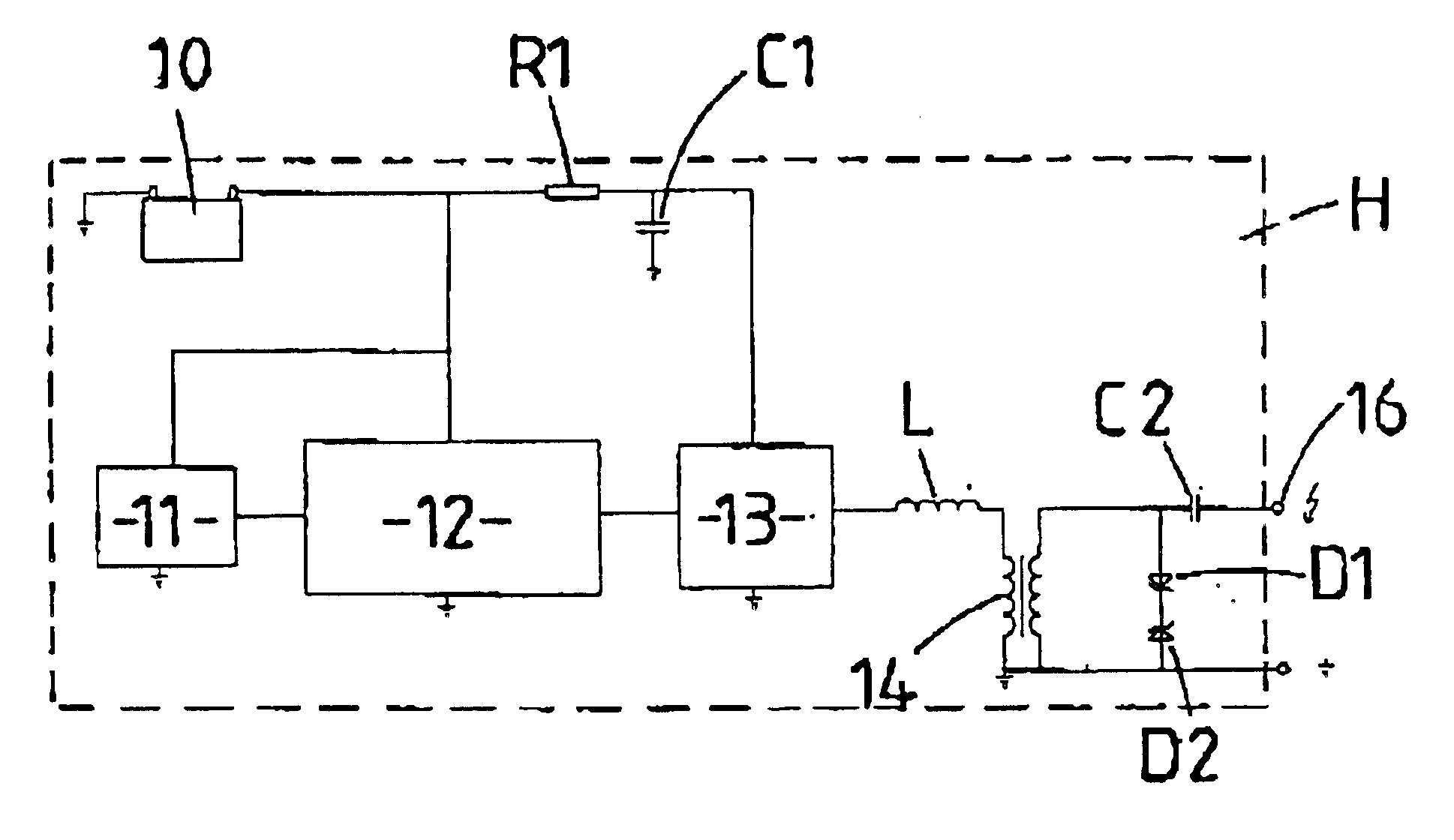
As mentioned previously the power source for the transmitting device is a small, lightweight battery 10 in this case a 9V battery. The componentry of the device is contained within a housing (indicated at “H”). A user interface 11 may consist of a number of lamps and / or a numerical or graphical display and / or a number of pushbutton or other types of switches.

The user interface 11 is connected to a control circuit 12 which will normally be built using one or a number of digital circuits such as a microcontroller. This control system 12 controls the lamps, controls what is shown on the display, reads the state of the switches and, when appropriate, produces a series of signals to the power interface circuit 13.

The power interface circuit 13 amplifies the signals generated by the control circuit 12. The power interface circuit 13 is not powered directly from the battery 10 but from an energy storage capacitor C1. The capacitor C1 is slowly charged by the battery 10 via resistor R1. In ...


PUM


Abstract

A data transmission system which is particularly useful for a remote control apparatus for an electric fence. The apparatus includes a portable hand held housing with a contact 16 which in use can contact a conductor of an electric fence line. The output of the apparatus includes a resonating circuit with inductor L, transformer 14 and a small high voltage capacitor C2. The apparatus can thus generate information embedded within a series of short signal bursts of a frequency within a predetermined frequency range. A receiver coupled to or forming part of an electric fence energizer can receive a signal from the apparatus to control operation of the energizer.

Description

BACKGROUND OF THE INVENTIONThis invention relates to improvements in data transmission, in particular data transmission along electric fences.Electric fences are used for a number of purposes, the most well known applications are for managing livestock or for building or property security purposes. The common form of an electric fence is where one or more conductors are held in place by fence posts, at a suitable height above the ground. The conductors are electrically insulated from the ground by suitable application of insulating materials. The conductors are connected to an apparatus commonly known as an electric fence energiser, which periodically applies an electric pulse of high voltage (usually in the range of 1 kV to 10 kV) and of short duration (usually less than 1 ms) to the conductors. When touching the electric fence, the electric pulse is experienced as unpleasant or painful, forming an effective deterrent against crossing or applying pressure to the electric fence.In m...

Claims


Application Information

Patent Timeline
Patent Type & Authority Patents(United States)
IPC IPC(8): G08B15/00
CPCH04L25/0266G08B15/005
Inventor LUNENBURG, PIETER CORNELISWOODHEAD, ROBERT CHARLES BRYAN
Owner TRU TEST
Why Eureka
Try Eureka