Electric motor controller

a technology of motor controller and motor rotation, which is applied in the direction of electronic commutators, dc motor speed/torque control, electric motor speed/torque regulation, etc., can solve the problems of loss of synchronization, large detection delay owing to sample holding, and inferior sine wave driving method in all motor vibration and noise, so as to achieve stable control of motor rotation, low noise, and high efficiency

Inactive Publication Date: 2005-02-01
PANASONIC CORP
View PDF12 Cites 40 Cited by
  • Summary
  • Abstract
  • Description
  • Claims
  • Application Information

AI Technical Summary

Benefits of technology

Object of the present invention is to provide an electric motor controller (hereinafter is referred to as motor controller) capable of stably

Problems solved by technology

Hence, the rectangular wave driving method is inferior to the sine wave driving method in all of motor vibration and noise.
However, a detection delay owing to sample holding is large in the feedback control wherein the zero-cross point is detected every electrical angle of 60 degrees.
This detection delay makes the operation of the motor unstable at a low speed in particular, thereby causing the loss of synchronization, and being apt to produce the problem of stopping the rotation of the motor.
Consequently, the rotation of the motor becomes uncontrollable in the end, thereby resulting in loss of synchronizati

Method used


Image

  • Electric motor controller
  • Electric motor controller
  • Electric motor controller

Examples


first embodiment

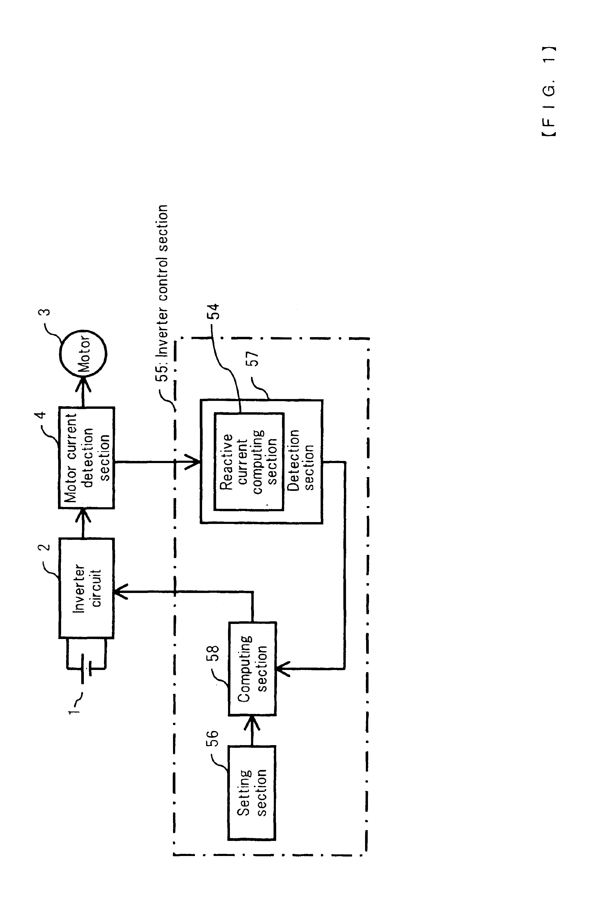
FIG. 1 is a block diagram showing a basic configuration of a motor controller in accordance with a first embodiment of the present invention. Referring to FIG. 1, the direct current of a DC power source 1 is applied to an inverter circuit 2 and converted into an alternating current. The alternating current is supplied to a motor 3 via a motor current detection section 4. The motor 3 is a synchronous brushless motor, for example, and not provided with position sensors for detecting the position of its rotor. The output of the motor current detection section 4 is input to a detection section 57 having a reactive current computing section 54. The detection section 57 is included in an inverter control section 55. The detection section 57 computes a reactive current and outputs a detected value on the basis of the value of the reactive current to a computing section 58. Various set values to control the inverter circuit 2 are set in a setting section 56, and these will be detailed later...

second embodiment

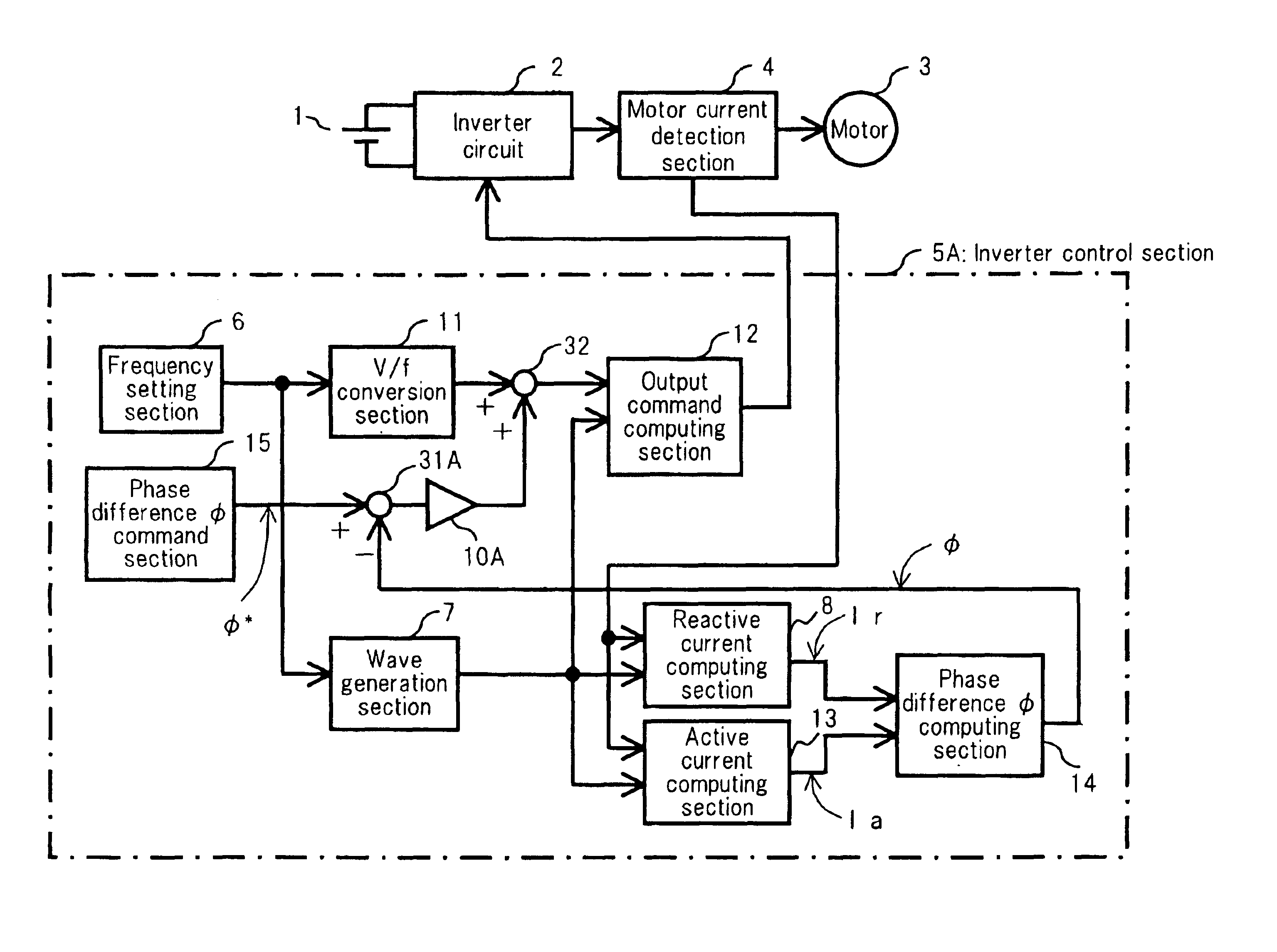
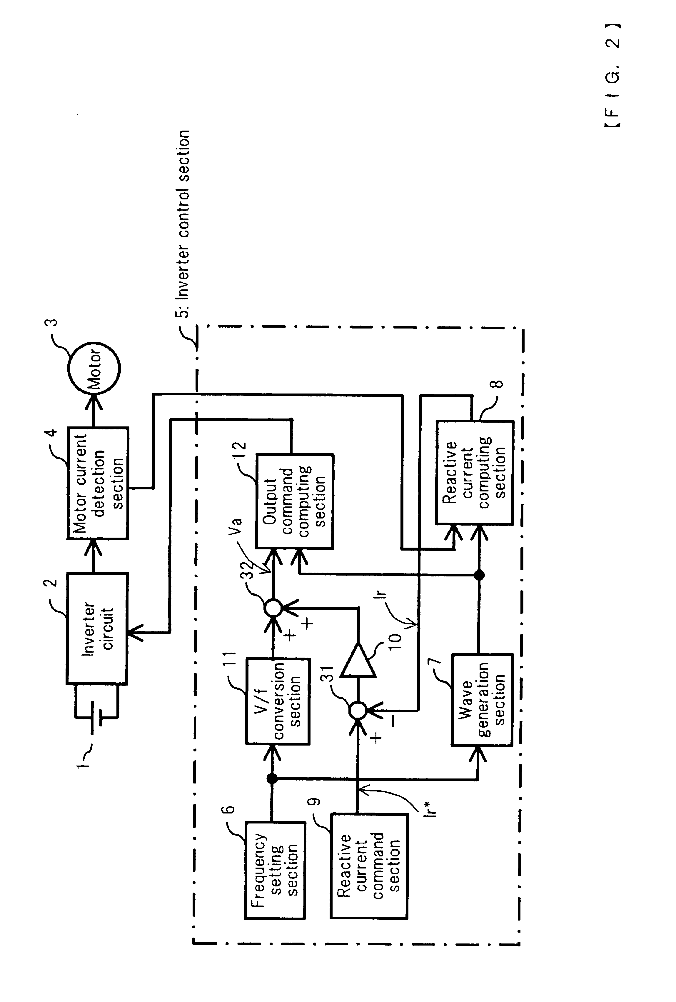
FIG. 4 is a block diagram showing a motor controller in accordance with a second embodiment of the present invention. In FIG. 4, an inverter control section 5A is obtained by adding an active current computing section 13 and a phase difference ø computing section 14 to the inverter control section 5 in the first embodiment shown in FIG. 2, and by replacing the reactive current command section 9 of the inverter control section 5 with a phase difference ø computing section 15. In the other configurations, the motor controller in the second embodiment is the same as that in the first embodiment. The phase difference ø is the phase difference between the applied voltage command value Va and the motor current Is. The active current computing section 13 obtains an active current Ia from the computation of Equation (4). Ia=23×{Iu×sin⁢ ⁢θ+Iv×sin⁡(θ-23⁢π)+Iw×sin⁡(θ-43⁢π)}(4)

The active current Ia obtained from the computation of Equation (4) is a component of the motor current Is in a directi...

third embodiment

FIG. 5 is a block diagram showing a motor controller in accordance with a third embodiment of the present invention. In FIG. 5, an inverter control section 5B is obtained by replacing the phase difference ø computing section 14 of the inverter control section 5A in the second embodiment shown in FIG. 4 with a phase difference α computing section 16 and by replacing the phase difference ø command section 15 of the inverter control section 5A with a phase difference α command section 17. The phase difference α computing section 16 computes a phase difference α from the output of the reactive current computing section 8, the output of the active current computing section 13 and a motor applied voltage command value, i.e., the output of the adder 32, by Equation (7). α=Tan-1⁡(R×IrVa-R×Ia)(7)

“R” in Equation (7) represents the resistance of a winding of one phase of the motor 3. The phase difference α indicated by an angle is the phase difference between the applied voltage command value ...


PUM


Abstract

The present invention provides a motor controller capable of driving a synchronous motor having no position sensor stably at high efficiency by carrying out simple control. In order to attain this purpose, a reactive current is obtained from a motor current and a rotation phase, an error voltage is obtained from the reactive current and the command value of the reactive current, thereby obtaining a motor applied voltage command value Va that is used to compensate for the V/f characteristic of the motor. Furthermore, the motor applied voltage command value Va is applied to an output command computing section, and computed with the rotation phase signal of a wave generation section, thereby obtaining a signal for PWM driving the switching devices of an inverter circuit.

Description

BACKGROUND OF THE INVENTIONThe present invention relates to an electric motor controller for controlling a synchronous motor without using any position sensors.A brushless motor is a representative example of a synchronous motor having no position sensor. A method of driving such electric motor is known as a conventional one wherein an induced voltage is detected to detect the position of the rotor of a brushless motor and the brushless motor is driven on the basis of the induced voltage. One of brushless motor driving methods is a rectangular wave driving method wherein a rectangular wave current flows through a brushless motor, and another is a sine wave driving method wherein a sine wave current flows therethrough. In the rectangular wave driving method, the waveform of the current is rectangular. Hence, the rectangular wave driving method is inferior to the sine wave driving method in all of motor vibration and noise. In the sine wave driving method, the zero-cross point of the ...

Claims


Application Information

Patent Timeline
IPC IPC(8): H02P6/00H02P6/06H02P27/06H02P6/08H02P6/18
CPCH02P6/002H02P6/08H02P6/06H02P6/28H02P6/18H02P27/06
Inventor NAKATA, HIDEKIYOSHIOKA, KANEHARUUEDA, MITSUOARAI, YASUHIRO
Owner PANASONIC CORP
Why Eureka
Try Eureka