Liquid crystal display device, optical element, method of fabricating the liquid crystal display device and method of making the optical element

optical element technology, applied in the direction of instruments, polarising elements, transportation and packaging, etc., can solve problems such as image persistence, and achieve the effect of improving performance and increasing the productivity of a liquid crystal display devi

Inactive Publication Date: 2005-02-08
SHARP KK
View PDF9 Cites 29 Cited by
  • Summary
  • Abstract
  • Description
  • Claims
  • Application Information

AI Technical Summary

Benefits of technology

[0021]In order to overcome the problems described above, an object of the present invention is to improve the performance and increase the productivity of a liquid crystal display device of the type including a high pretilt angle region (i.e., vertical alignment region) and a low pretilt angle region (i.e., a horizontal alignment region) such as the OCB-mode LCD and the HAN-mode LCD described above.
[0022]Another object of the present invention is to provide a material of a liquid crystal alignment film that can be used effectively to form the high and low pretilt angle regions with high stability and efficiency and an optical element made of such a material.

Problems solved by technology

As a result, the image to be displayed is sometimes not refreshed, thus causing a so-called “image persistence” problem.
A similar problem also happened even when a vertical alignment film was exposed to a polarizing ultraviolet ray as disclosed in Japanese Laid-Open Publication No. 11-311788.

Method used


Image

  • Liquid crystal display device, optical element, method of fabricating the liquid crystal display device and method of making the optical element
  • Liquid crystal display device, optical element, method of fabricating the liquid crystal display device and method of making the optical element
  • Liquid crystal display device, optical element, method of fabricating the liquid crystal display device and method of making the optical element

Examples


embodiment 1

[0074]A polymer material, which includes a polyimide skeleton as its main chain with horizontal alignment properties and an alkyl group as its side chains with vertical alignment properties to be bonded to the main chain, is prepared as an alignment film material. The general molecular structure of this alignment film material is represented by the following Chemical Formula (1):

[0075]where X may be one of the five types of atomic groups represented by the following Chemical Formula (2) or a mixture (i.e., copolymer) thereof, and Y is an alkyl chain in this preferred embodiment. The alkyl chain Y is introduced for each repeating unit represented by Chemical Formula (1) (i.e., has an introduction percentage of 100%).

[0076]Three types of thermoplastic polyimide-based alignment film materials, which included a benzoyl ether group, a benzoyl peroxide group and an amide group as spacers that bonded the polyimide main chain and the alkyl side chains together, respectively, were prepared...

embodiment 2

[0093]Hereinafter, a second specific preferred embodiment of the present invention will be described. The second preferred embodiment relates to a liquid crystal display device that is fabricated by using the alignment film material according to any of the preferred embodiments of the present invention described above.

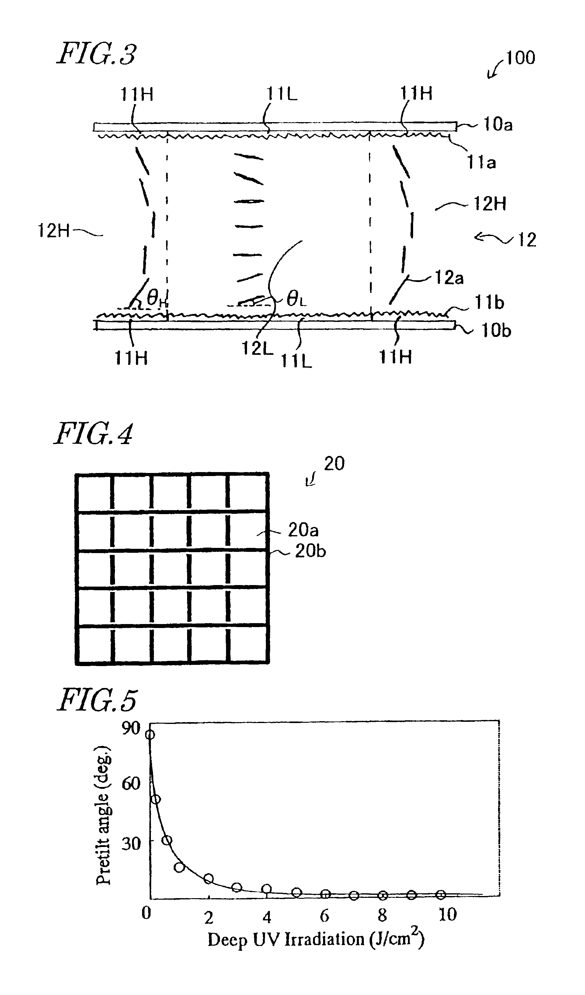
[0094]First, samples of the OCB-mode LCD shown in FIG. 3 were fabricated in the following manner as LCD 1, LCD 2, LCD 3 and LCD 4 representing two specific Examples 1 and 2 of the present invention and two Comparative Examples 1 and 2, respectively.

[0095]As for the LCD 1 representing Example 1, the alignment film material representing Example 2 of the first preferred embodiment described above (i.e., a polyimide-based alignment film material including benzoyl peroxide spacers) was used.

[0096]As for the LCD 2 representing Example 2, the alignment film material representing Example 4 of the first preferred embodiment described above (i.e., a polyvinyl alcohol-based align...


PUM

PropertyMeasurementUnit
pretilt angleaaaaaaaaaa

Abstract

A liquid crystal display device includes two substrates, a liquid crystal layer sandwiched between the substrates and two alignment films, each being provided on one surface of associated one of the substrates so as to face the liquid crystal layer. The device defines multiple picture elements. At least one of the two alignment films is made of a polymer material that includes a main chain, an atomic group having a bond that is selectively cut when exposed to an actinic ray and a side chain bonded to the main chain via the atomic group. The polymer material with the side chain can give a pretilt angle of greater than 85 degrees but 90 degrees or less to liquid crystal molecules. The polymer material without the side chain can give a pretilt angle of 2 degrees to 15 degrees to the liquid crystal molecules.

Description

BACKGROUND OF THE INVENTION[0002]1. Field of the Invention[0003]The present invention relates to a liquid crystal display device (LCD), an optical element, a method of fabricating the LCD and a method of making the optical element. The present invention also relates to a material of a liquid crystal alignment film that can be used effectively in the LCD or the optical element.[0004]2. Description of the Related Art[0005]LCDs are used extensively today in portable telecommunications units such as cell phones, personal computers, word processors, amusement appliances, flat panel displays for TV sets, for example, and display boards, windows, doors and walls by utilizing the optical shuttering effects of their liquid crystal layer.[0006]An LCD conducts a display operation by utilizing the optical anisotropy of its liquid crystal molecules. Accordingly, in an LCD, the orientation directions of the liquid crystal molecules are controlled. The orientation directions of liquid crystal mole...

Claims


Application Information

Patent Timeline
Patent Type & Authority Patents(United States)
IPC IPC(8): G02F1/1337G02F1/13G02F1/139
CPCG02F1/133753G02F1/1395G02F1/133788Y10T428/1005G02F2001/133761C09K2323/02G02F1/133761G02F1/1337
Inventor MIZUSAKI, MASANOBUKAWAMURA, TADASHIFUJII, AKIYOSHIYAMADA, YUICHIRO
Owner SHARP KK
Why Eureka
Try Eureka