

Electroless gold plating solution
- Summary
- Abstract
- Description
- Claims
- Application Information
AI Technical Summary
Benefits of technology
Problems solved by technology
Method used
Image

Examples
example 1
A Ni—P coating was formed on a copper plate by the above-mentioned procedure using ICP Nicoron GM manufactured by Okuno Chemical Industries Co., Ltd. and then subjected to electroless gold plating using solution No. 1 in Table 1.
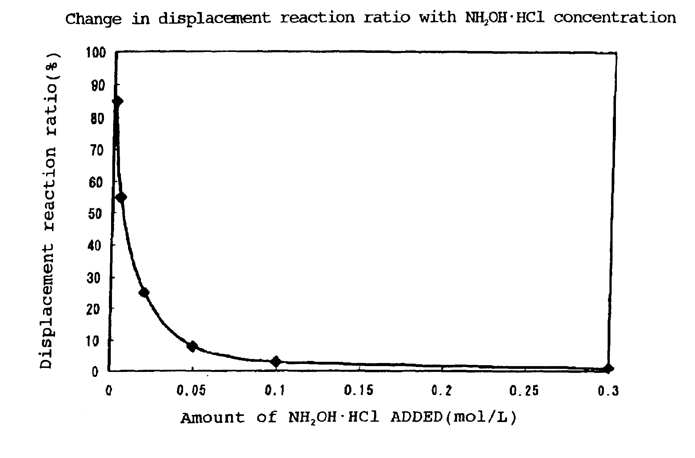
As a result of immersion for 1 hr. with stirring at 60° C., a bright yellow semigloss gold coating having a thickness of 0.04 μm was obtained. The coating thus obtained did not peel off in a tape test, thus showing good adhesion, and almost no pores were observed. The displacement reaction ratio based on the amount of Ni eluted was 27%. The Au wire bonding strength of at least 10 gf was excellent.
example 2
A Ni—P coating was formed on a copper plate by the above-mentioned procedure using ICP Nicoron GM manufactured by Okuno Chemical Industries Co., Ltd. and then subjected to electroless gold plating using solution No. 2 in Table 1.
As a result of immersion for 1 hr. with stirring at 60° C., a bright yellow semigloss gold coating having a thickness of 0.68 μm was obtained. The coating thus obtained did not peel off in a tape test, thus showing good adhesion, and no pores were observed. The displacement reaction ratio based on the amount of Ni eluted was 1%.
example 3
A Ni—P coating was formed on a copper plate by the above-mentioned procedure using ICP Nicoron GM manufactured by Okuno Chemical Industries Co., Ltd. and then subjected to electroless gold plating using solution No. 3 in Table 1.
As a result of immersion for 1 hr. with stirring at 60° C., a bright yellow semigloss gold coating having a thickness of 0.08 μm was obtained. The coating thus obtained showed good adhesion in a tape test, and almost no pores were observed. The displacement reaction ratio based on the amount of Ni eluted was 15%.
PUM
| Property | Measurement | Unit |
|---|---|---|
| Fraction | aaaaa | aaaaa |
| Fraction | aaaaa | aaaaa |
| Temperature | aaaaa | aaaaa |
Abstract
Description
Claims
Application Information