Fuel cell having a corrosion resistant and protected cathode catalyst layer

a cathode catalyst, corrosion-resistant technology, applied in the field of fuel cells, can solve the problems of high corrosion area, high corrosion area, and corrosion of the cathode catalyst layer opposite the area of inadequate hydrogen, and achieve high corrosion area, minimize corrosion, and high corrosion area

Inactive Publication Date: 2005-02-15
AUDI AG
View PDF6 Cites 66 Cited by
  • Summary
  • Abstract
  • Description
  • Claims
  • Application Information

AI Technical Summary

Benefits of technology

In a further preferred embodiment, the cathode catalyst layer defines a reactive surface secured adjacent to an electrolyte wherein the platinum oxygen reduction catalyst is, uniformly applied across the reactive surface of the cathode catalyst layer and the oxygen evolution catalyst is non-uniformly applied across the reactive surface of the cathode catalyst layer. High corrosion areas of the reactive surface of the cathode catalyst layer receive the oxygen evolution catalyst, or they receive a higher proportion of the oxygen evolution catalyst than low corrosion areas of the reactive surface of the cathode catalyst layer. It has been discovered that specific areas of a cathode catalyst layer reactive surface corrode more rapidly than other areas, and such high corrosion areas frequently result from design aspects of flow paths of a reducing fluid stream passing adjacent an opposed fuel flow path. Some areas of a reactive surface of the anode catalyst layer have inadequate hydrogen concentrations to support an average current density of the anode catalyst layer resulting in corrosion of the cathode catalyst layer opposite the area of inadequate hydrogen on the anode catalyst layer. Application of the oxygen evolution catalyst to such high corrosion areas of the reactive surface of the cathode catalyst layer will minimize corrosion in those areas.
In an additional preferred embodiment carbon support materials, such as an amorphous high surface area carbon black that supports the cathode catalysts, and / or an amorphous carbon support layer secured adjacent to the cathode catalyst may be replaced by a heat-treated carbon that resists electrochemical oxidation thereby further minimizing corrosibn of the cathode catalyst layer.
In another preferred embodiment of a fuel cell having a corrosion resistant and protected cathode catalyst layer, the anode catalyst layer includes a catalyst that inhibits an oxygen reduction reaction at the anode catalyst layer, such as in Region B of FIG. 1, during start up of the fuel cell or under oxidizing conditions. The poor oxygen reduction catalyst therefore reduces a total current in Region B, minimizing corrosion there compared to an anode catalyst layer consisting of only a platinum catalyst. Appropriate oxygen reduction catalysts may be in the form of a metal black or may be supported on a suitable support material known in the fuel cell art such as carbon black. The oxygen reduction catalysts may be a pure material, an alloy of two or more materials, or an admixture of two or more materials. Exemplary oxygen reduction catalysts include iridium, rhodium, palladium, rhenium, ruthenium, gold, silver, nickel, alloys of these materials with each other or with platinum, and mixtures thereof.

Problems solved by technology

It has been discovered that specific areas of a cathode catalyst layer reactive surface corrode more rapidly than other areas, and such high corrosion areas frequently result from design aspects of flow paths of a reducing fluid stream passing adjacent an opposed fuel flow path.
Some areas of a reactive surface of the anode catalyst layer have inadequate hydrogen concentrations to support an average current density of the anode catalyst layer resulting in corrosion of the cathode catalyst layer opposite the area of inadequate hydrogen on the anode catalyst layer.

Method used


Image

  • Fuel cell having a corrosion resistant and protected cathode catalyst layer
  • Fuel cell having a corrosion resistant and protected cathode catalyst layer
  • Fuel cell having a corrosion resistant and protected cathode catalyst layer

Examples


Embodiment Construction

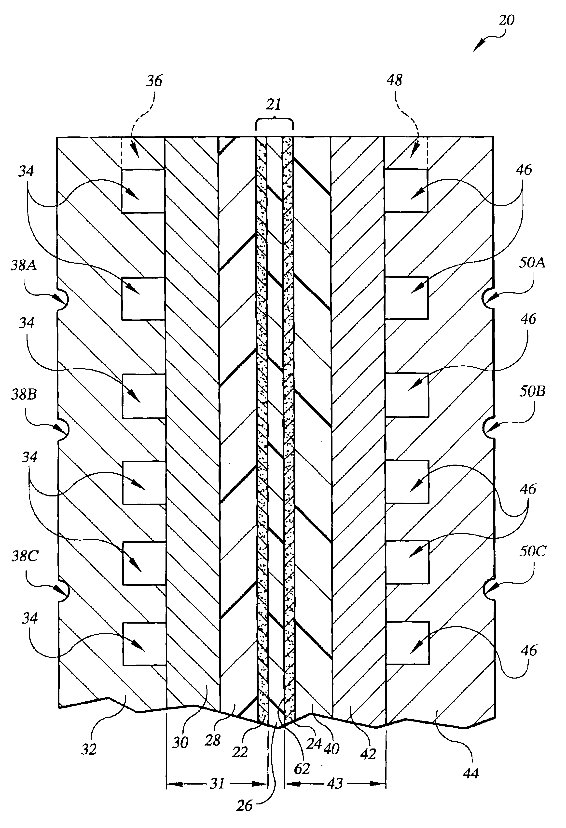
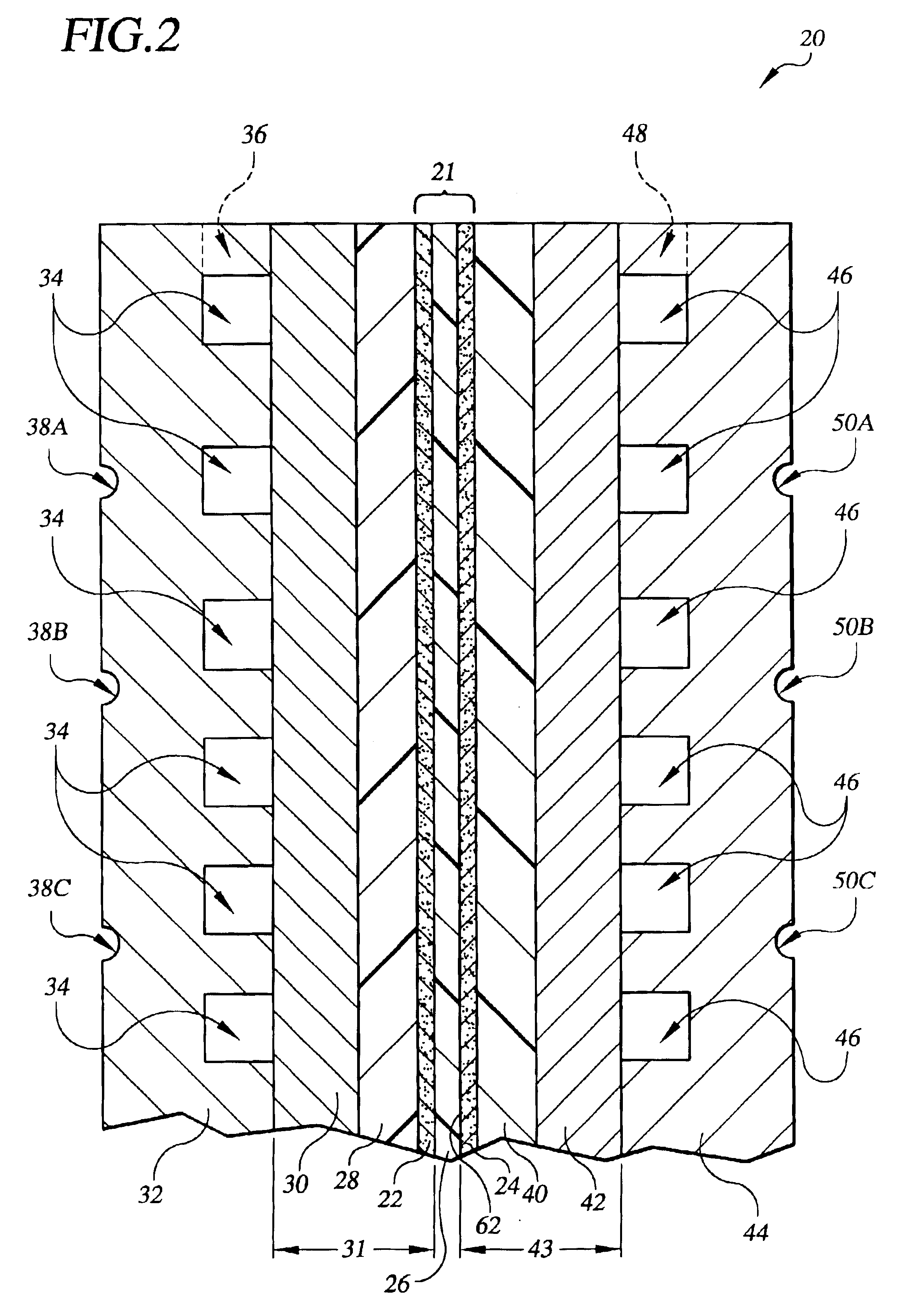
Referring to the drawings in detail, a fuel cell having a corrosion resistant and protected cathode catalyst layer is shown schematically in cross-section in FIG. 2, and is generally represented by the reference numeral 20. The fuel cell 20 includes a membrane electrode assembly 21 consisting of an anode catalyst layer 22 a cathode catalyst layer 24 secured to opposed sides of an electrolyte 26. The fuel cell 20 may also include an anode catalyst layer support means, consisting of one or more porous layers for supporting the anode catalyst layer 22 and for permitting fluid flow through the anode support means. The one or more porous layers of the anode catalyst layer support means may include an anode diffusion layer 28 secured adjacent to the anode catalyst layer 22 and an anode substrate layer 30 secured adjacent to the anode diffusion layer 28. The anode catalyst layer 22, anode diffusion layer 28 and anode substrate 30 may also be characterized as an anode electrode 31.

An anode ...


PUM

PropertyMeasurementUnit
temperatureaaaaaaaaaa
voltageaaaaaaaaaa
voltageaaaaaaaaaa

Abstract

The invention is a fuel cell (20) having a corrosion resistant and protected cathode catalyst layer (24). The cathode catalyst layer (24) includes a platinum oxygen reduction catalyst and an oxygen evolution catalyst selected from the group consisting of catalysts that are more active than platinum for oxygen evolution. The oxygen evolution catalyst may be uniformly applied within the cathode catalyst layer, or non-uniformly applied to identified high corrosion areas (82) (84) of the cathode catalyst layer (24). The cathode catalyst layer (24) may include heat-treated carbon support material, and/or a heat-treated carbon black within a diffusion layer (40) supporting the cathode catalyst layer (24). The fuel cell (20) may also include an anode catalyst layer (22) having a poor oxygen reduction catalyst having a greater oxygen reduction over potential than platinum.

Description

TECHNICAL FIELDThe present invention relates to fuel cells that are suited for usage in transportation vehicles, portable power plants, or as stationary power plants, and the invention especially relates to a fuel cell that resists cathode catalyst corrosion upon start up and shut down of the fuel cell.BACKGROUND ARTFuel cells are well known and are commonly used to produce electrical energy from hydrogen containing reducing fluid and oxygen containing oxidant reactant streams to power electrical apparatus such as motors, and transportation vehicles, etc. In fuel cells of the prior art, it has been discovered that, upon start up of fuel cells, corrosion takes place on catalyst layers of electrodes, and especially on cathode catalyst layers. That corrosion leads to performance loss of the cathode catalyst layers and the fuel cells.In starting up known fuel cells that contain air on both anode and cathode catalyst layers and that employ a proton exchange membrane “PEM” as an electroly...

Claims


Application Information

Patent Timeline
Patent Type & Authority Patents(United States)
IPC IPC(8): H01M4/86H01M4/90H01M4/92H01M4/96H01M8/10H01MH01M4/88H01M8/02
CPCH01M4/8605H01M4/92H01M4/926H01M8/1002Y02E60/521H01M4/921H01M8/1007Y02E60/50
Inventor BETT, JOHN A. S.CIPOLLINI, NED E.JARVI, THOMAS D.BREAULT, RICHARD D.
Owner AUDI AG
Why Eureka
Try Eureka