Method and apparatus for determining the polarization properties of light emitted, reflected or transmitted by a material using a laser scanning microscope

a laser scanning microscope and polarization technology, applied in the direction of electrical devices, instruments, photoelectric discharge tubes, etc., can solve the problems of not providing satisfying, method does not provide any information on anisotropy and many other physical interactions of the sample, and the intensity variation of the illuminating laser light is not satisfying

Inactive Publication Date: 2005-02-15
MAGYAR TUDOMANYOS ACAD SZEGEDI BIOLOGIAI KOEZP
View PDF14 Cites 53 Cited by
  • Summary
  • Abstract
  • Description
  • Claims
  • Application Information

AI Technical Summary

Benefits of technology

Measurements in a confocal mode include also the step of selecting the light component received from the focus point of the laser light on the sample and excluding the light components received from points other than the focus point. This enables the optical slicing of the sample.
According to a further aspect of the invention a laser light that allows spatial and/or temporal intensity concentration is used for illuminating the sample and for causing two or more photon excita

Problems solved by technology

Nevertheless these methods do not provide any information on the anisotropy and many other physical interactions of the sample that may only be examined with polarization spectroscopy methods.
Although this method may be carried out with the accessories of the Zeiss LSM 410, it does not provide satisfying results because of the variation of the intensity of fluorescence in time—especially in biological samples.
A further problem may be the variation of the intensity of the illuminating laser light.
Vibrations and movements of the sample or the stage may also lead to significant distortion.
One drawback of this configuration is that in most of the LSM-s the confocal mode is not available during LD, CD and birefringence measurements which can only

Method used


Image

  • Method and apparatus for determining the polarization properties of light emitted, reflected or transmitted by a material using a laser scanning microscope
  • Method and apparatus for determining the polarization properties of light emitted, reflected or transmitted by a material using a laser scanning microscope
  • Method and apparatus for determining the polarization properties of light emitted, reflected or transmitted by a material using a laser scanning microscope

Examples


Embodiment Construction

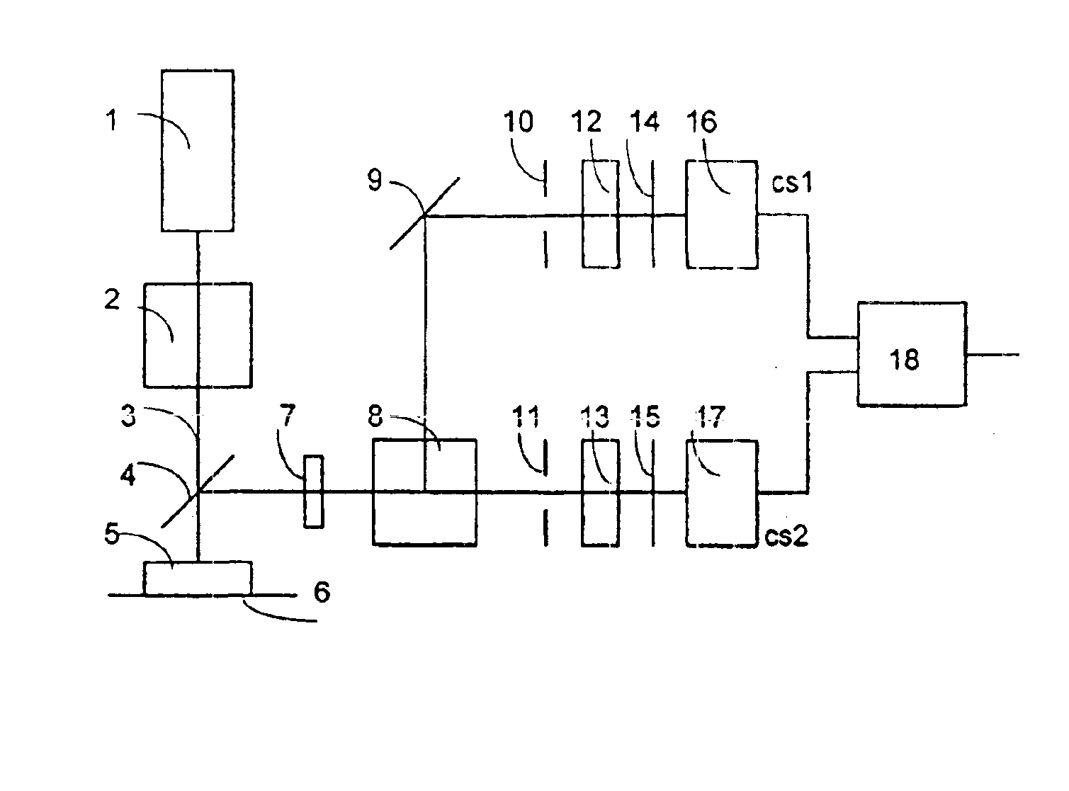
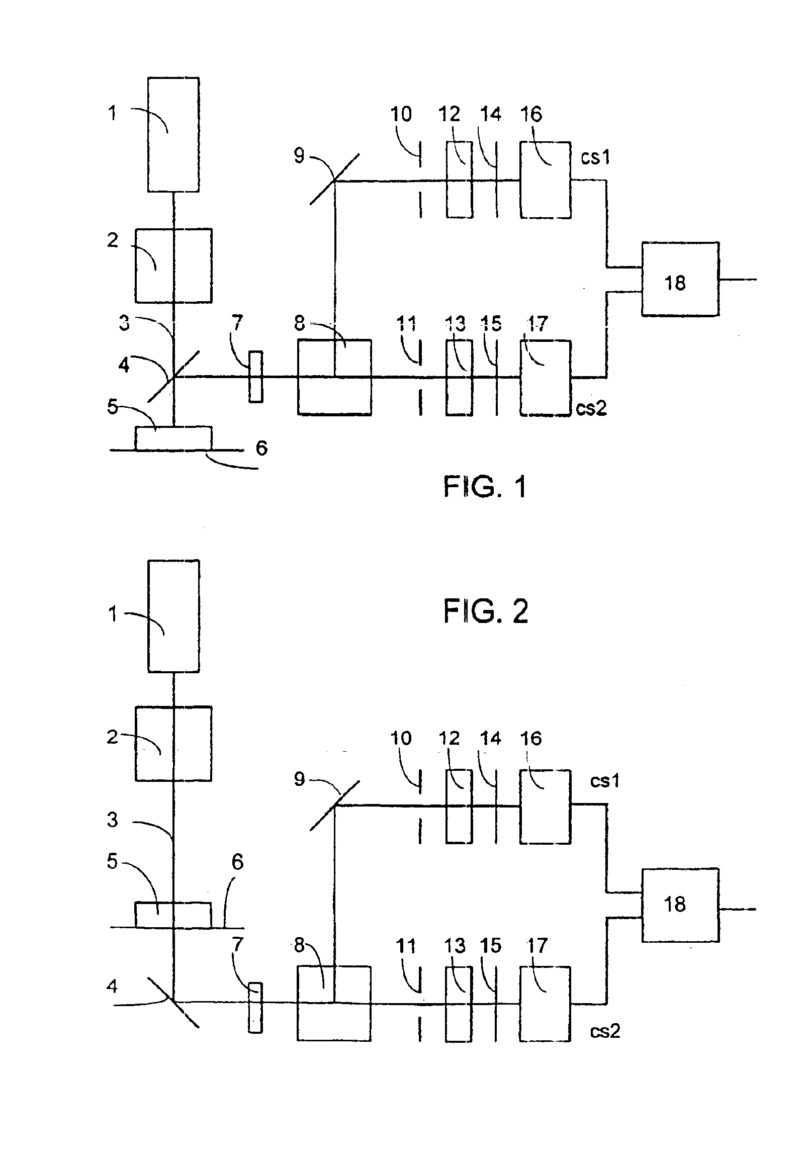
FIG. 1 depicts a two channel configuration with a sample 5 on object table 6 which is illuminated with a laser light of laser light source 1 with the laser light routed through polarization state setting unit 2. The reflected light or the fluorescence are deflected by beam splitter 4 (for example semitransparent mirror). This way two light beams are generated by a second beam splitter 8. In both light beams there is a detector 16 and 17 producing an output signal proportional with the intensity of light which is input to signal processing units 18. In each of the channels cs1 and cs2 the intensity of only one polarization component is measured. A semitransparent mirror can be used as a beam splitter 8. In this case the entering light beam will be separated in a given proportion of the intensity. In one of the divided light beams a further mirror 9 may be placed for deflecting a selected light beam. Both of the divided (deflected) light beams contain all polarization components, ther...


PUM


Abstract

The invention relates to a method and apparatus for determining the polarization properties of light emitted, reflected or transmitted by a material using a laser scanning microscope with the tested material being illuminated point by point with a laser beam of known polarization state. According to the invention the light beam with a polarization state modified by the material or the light emitted by the material is being examined by measuring the intensity of two different polarization components of a selected light beam received from each point of said material essentially at the same time and assigning a signal obtained by processing the two intensity signals to a respective point of an image of said material. The apparatus has a polarization state generator between the laser light source and the material being tested, and a detector in a light beam for determining the intensity of light with a polarization state modified by the material or the intensity of light emitted by the material, the improvement of which is that a means for dividing the polarization components in space or time is used in front of the detector.

Description

FIELD OF THE INVENTIONThe invention relates to a method and apparatus for determining the polarization properties of light emitted, reflected or transmitted by a material using a laser scanning microscope.BACKGROUND OF THE INVENTIONUsing a laser scanning microscope (LSM) selected points (well defined volume units) of the tested material are irradiated by a focused laser beam in response of which information on the intensity of the transmitted, reflected or emitted light is obtained which can be stored generally in digital form. The signal of the laser scanning microscope during scanning a field of predetermined width and length is used to obtain a picture of high resolution for detailed analysis. The picture quality may be further increased by using the LSM in confocal mode, thereby substantially excluding the disturbing effect of the light emanating from points other than the focus point. In most of the commercially available laser scanning microscopes (such as in Zeiss 410 or 510)...

Claims


Application Information

Patent Timeline
IPC IPC(8): G02B21/00G01N21/21G01J4/00G01J4/04G01N21/19G01N21/23G01N21/64
CPCG02B21/002G01N21/21G01J4/04
Inventor GARAB, GYOZOPOMOZI, ISTVANWEISS, GEORGJORGENS, REINHARD
Owner MAGYAR TUDOMANYOS ACAD SZEGEDI BIOLOGIAI KOEZP
Why Eureka
Try Eureka