Method of cleaning passageways using a mixed phase flow of a gas and a liquid

Inactive Publication Date: 2005-02-22
OLYMPUS CORP
View PDF74 Cites 57 Cited by
  • Summary
  • Abstract
  • Description
  • Claims
  • Application Information

AI Technical Summary

Benefits of technology

lengths of tubing is a significant advantage of the present invention. This requires operating in the appropriate region of parameter space so that the gas is able to form and entrain droplets repeatedly by means of the hydrodynamic instability. It can be estimated that prior art techniques which use a total of only a drop or two of liquid would not provide enough liquid for the surface area of a dental handpiece tube to achieve significant re-formation of droplets. One or two drops equals tenths of a milliliter. The present method uses a continuous flow for a period of time such that the amount of liquid used for the same purpose would be tens of milliliters, some two orders of magnitude higher.
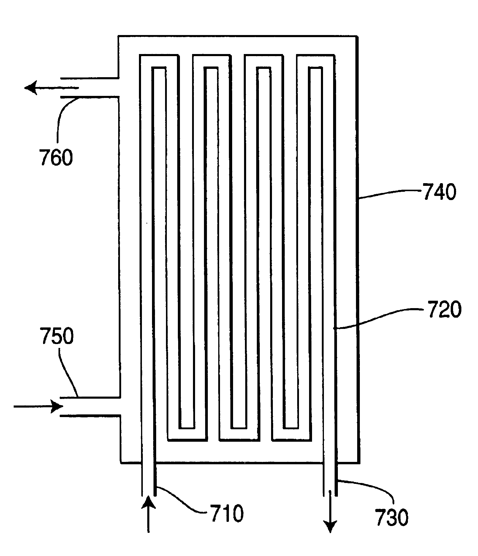
Additionally, some geometries which are capable of being cleaned by the present invention have abrupt changes of geometry such as right-angle elbow or U-bends. It might be expected that at such changes of direction, many of the droplets will impact the elbow or bend and coalesce, which presents a danger of depleting the population of droplets which are the supposed mechanism of erosion. Nevertheless, it will be shown hereinbelow that good cleaning using the method of the present invention has been observed in passageways which have as many as seven reversals of direction. This indicates that the appropriate mixed-phase flow condition re-establishes itself quite well within a short distance after such a disturbance.
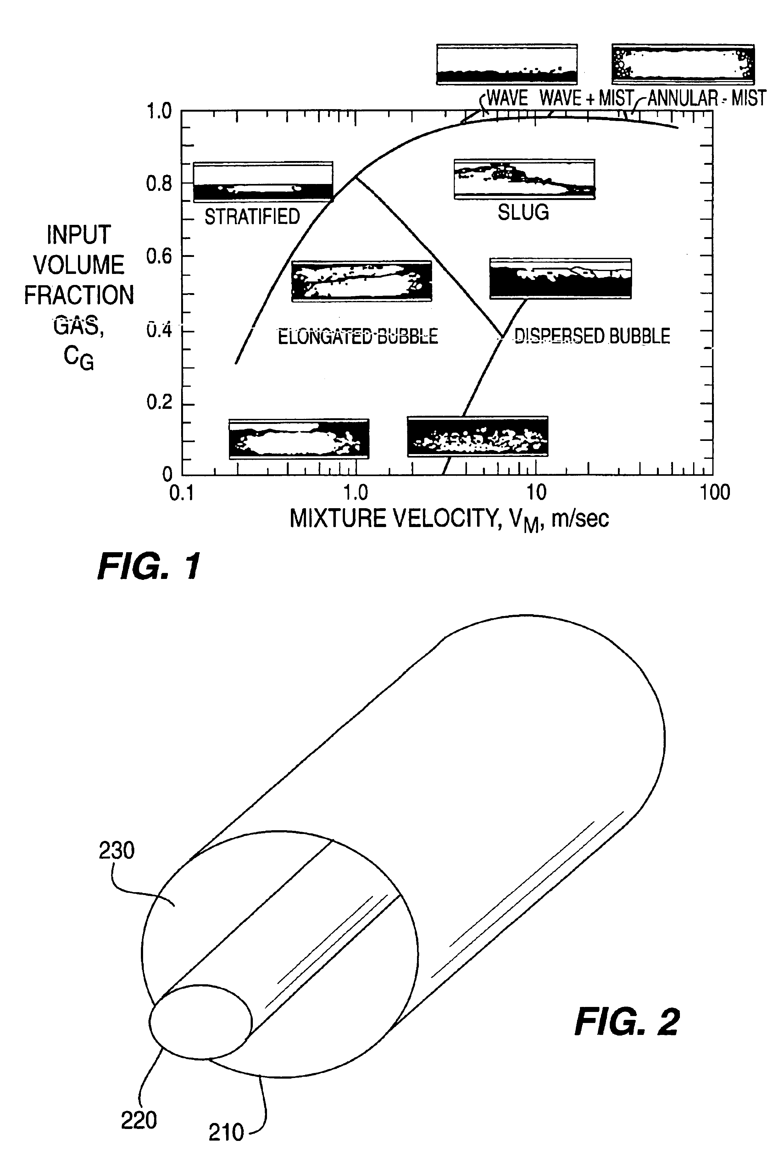
The formation and re-formation of droplets is influenced by, among other parameters, the surface tension of the liquid, the viscosity of the liquid, and the velocity of the gas relative to a liquid layer on the wall. In regard to surface tension, it is believed that, particularly for small diameter tubing, it is important that the liquid have a lower surface tension than pure water, which is about 72 dynes/cm. The addition of typical surfactants can lower that value to as low as 17 dynes/cm, depending on the specific surfactant added and its concentration. It is believed that a surface tension lower than about 72 dyne/cm, but higher than about 17 dyne/cm, encourages the formation of an appropriately small droplet size. It is believed that such a size results in high l

Problems solved by technology

Interior surfaces of passageways such as small-bore tubing, pipes, ducts and the like, which may carry fluids such as liquids, gases, slurries or aerosols, are very difficult to clean and to maintain in a clean condition.
When the flow path is long and narrow, or hard to reach, it is difficult to clean the surfaces by conventional liquid phase flushing because such a long, narrow passageway limits liquid flow velocities by creating a high resistance to flow.
As a result, shear stresses which could aid in the removal of contaminants from such surfaces are limited.
Low flow velocities also limit the usefulness of solvents for the same reasons.
Cleaning of small diameter passageways is also difficult because of the nature of certain types of residues.
Removal of biofilm from passageways is also necessary for other applications, including medical, industrial and food service applications, because such biofilms are the main cause of high bacterial counts and high levels of endotoxins.
However, removing biofilm from fluid passageways is quite difficult, which makes disinfecting the surface more difficult as well.
However, these agents do not readily diffuse into the entire thickness of the biofilm.
Thus these treatments are generally only partially effective, and the original levels of viable bacteria return quite rapidly.
However, in addition to the fact that autoclaving does not actually remove debris from the handpiece, this autoclaving procedure can be damaging to the turbine and various seals in the han

Method used


Image

  • Method of cleaning passageways using a mixed phase flow of a gas and a liquid
  • Method of cleaning passageways using a mixed phase flow of a gas and a liquid
  • Method of cleaning passageways using a mixed phase flow of a gas and a liquid

Examples


example 1

This example illustrates cleaning of a dental handpiece having a complex internal geometry. The flow path of fluid through the handpiece is shown generally in FIG. 4, except that the return path is divided into a number of angularly spaced subdivisions. The internal diameter of the tubing varied from {fraction (1 / 32)} to {fraction (1 / 16)} inch. The tubing was thoroughly cleaned between experiments.

The handpiece was inoculated with an initial bacterial load of 4×10⁶ Bacillus steariothermopholia spores (ATCC 7953) distributed among four chosen sites experimentally known to be the worst sites for cleaning.

The handpieces were then subjected to various cleaning techniques as set forth below. Then the cleaned handpieces were placed in sterile growth medium, and incubated for two days. The bacterial growth was then measured.

Part A. Surfactant Only.

The cleaning solution was a surfactant available as CPC-718 from VWR Scientific, which is a mixture of amphoteric and anionic surfactants. The s...

example 2

The method of Example 1 was repeated but cleaning the internal water line channel of the dental handpiece, which was a simple tubular passageway. Similar results were obtained.

example 3

A biopsy device containing a cable inside a polymer-coated sheath, having an outside diameter of 0.084 inch, was used in this example. The access for fluid flow to clean the region between the cable and the sheath was at each end of the sheath where the cable entered or exited from the sheath using existing clearances. Cleaning between the sheath and the cable was tested by connecting the flow source to an existing threaded connection at the operator's end of the biopsy device. The flow then exited at the other end of the biopsy device where the tissue removal blades are located.

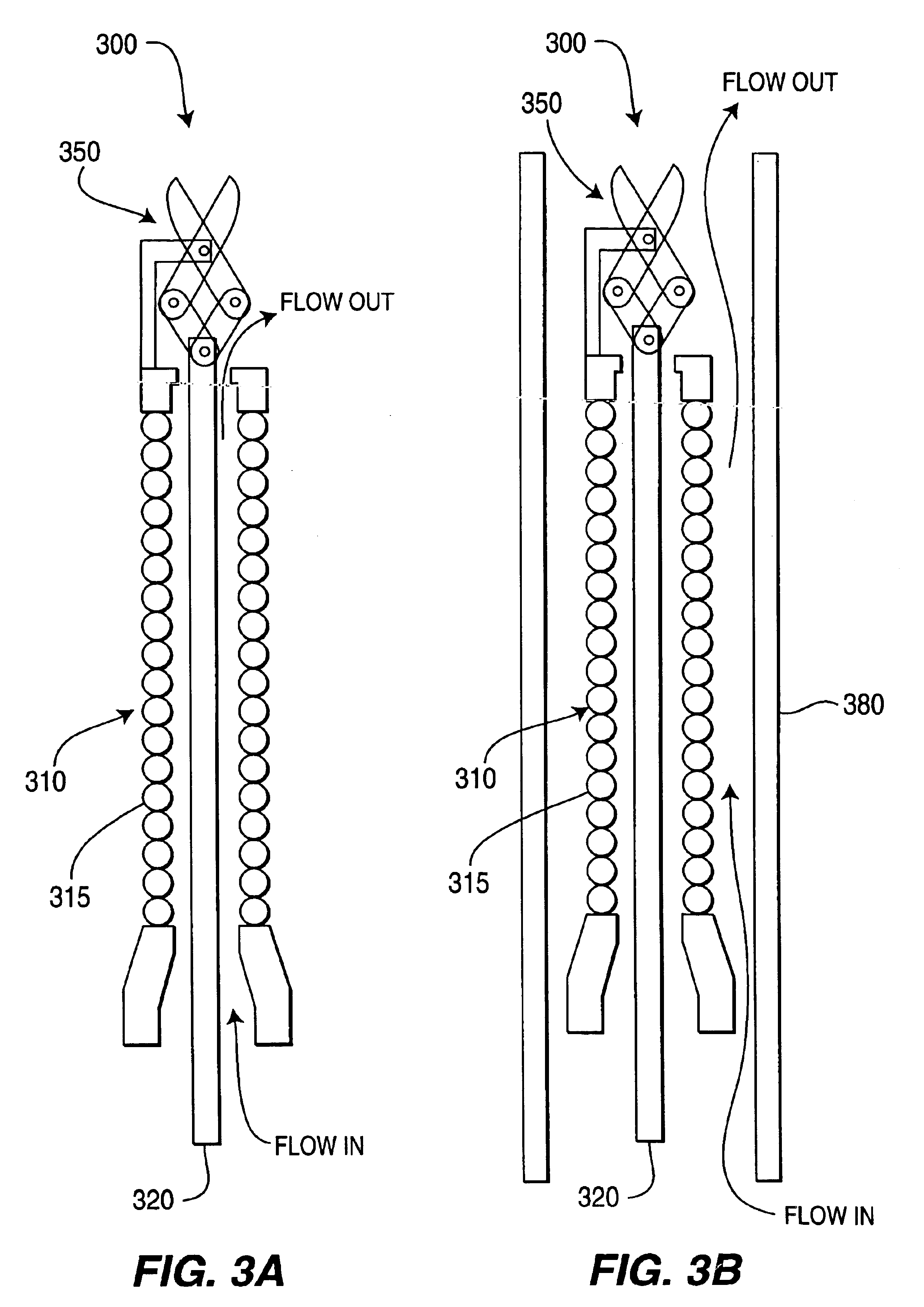
For cleaning the exterior of the biopsy device, the entire length of the device was inserted into a clear plastic tube which served as a passageway to direct flow along the outside of the device. The inside diameter of the clear plastic tube was about 50% larger than the outside diameter of the device.

Air was supplied at a pressure of 50 psi, and a gas / liquid flow rate ratio of several hundred to one, using ...


PUM

PropertyMeasurementUnit
Temperatureaaaaaaaaaa
Pressureaaaaaaaaaa
Velocityaaaaaaaaaa

Abstract

A method of cleaning surfaces using a mixed phase cleaning mixture of an aqueous solution and a flow of gas sufficient to produce droplets of the liquid which are entrained by the gas for a time sufficient to clean tubing of various lengths and geometries and porous membranes to remove biofilm, debris and contaminants.

Description

BACKGROUND OF THE INVENTIONInterior surfaces of passageways such as small-bore tubing, pipes, ducts and the like, which may carry fluids such as liquids, gases, slurries or aerosols, are very difficult to clean and to maintain in a clean condition. When the flow path is long and narrow, or hard to reach, it is difficult to clean the surfaces by conventional liquid phase flushing because such a long, narrow passageway limits liquid flow velocities by creating a high resistance to flow. As a result, shear stresses which could aid in the removal of contaminants from such surfaces are limited. Low flow velocities also limit the usefulness of solvents for the same reasons.Cleaning of small diameter passageways is also difficult because of the nature of certain types of residues. Fluid passageways which supply water, even purified water, develop bacterial and fungal growth from the water on their interior surfaces, as is well known. Bacteria present in the water strongly adhere to tubing ...

Claims


Application Information

Patent Timeline
IPC IPC(8): A61C1/00A61L2/22A61L2/18A61M1/16B01D65/06B01D65/02B01D65/00B08B9/02C23G5/00C11D11/00C11D3/02C11D3/14C11D3/39C11D3/395C11D3/48A61C17/00A61C19/00A61M1/14B08B3/08B08B3/10B08B9/027B08B9/032
CPCA61C1/0076A61M1/1682A61L2/22A61M1/169B01D65/02B01D65/022B08B9/032B08B9/0326B08B9/0327C11D3/042C11D3/044C11D3/14C11D3/3947C11D3/3956C11D3/48C11D11/0041C23G5/00A61L2/186A61L2202/24B01D2321/04B01D2321/2066B08B2209/022
Inventor LABIB, MOHAMED EMAMLAI, CHING-YUEMATERNA, PETER A.MAHON, GEOFFREY LAWRENCE
Owner OLYMPUS CORP
Why Eureka
Try Eureka