Electrical connector

Inactive Publication Date: 2005-02-22
THE FUJIKURA CABLE WORKS LTD
View PDF2 Cites 60 Cited by
  • Summary
  • Abstract
  • Description
  • Claims
  • Application Information

AI Technical Summary

Benefits of technology

It is an object of the invention to provide an improved electrical connector which eliminates all the disadvantages of the prior art and which is well-adapted to high speed transmission signals and easy to manufacture without any need to give an attention t

Problems solved by technology

Therefore, forming a circuit with a good transmission line becomes very difficult because to the space is far too small for the lead wires.
However, the electroless plating is time-consuming.
Therefore, a flexible circuit board must be kept immersed in a plating bath which is alkaline for a long period of time, creating a risk of copper foils on the board being partially peeled or removed.
In such an electrical connector, moreover, it is difficult to embed the fine lead wires in an elastomer layer or board in a manner such that the overall lengths of the fine lead wires are exactly embedded in the elastomer layer with its thickness completely coincident with the lengths of the fine lead wires.
As a result, the fine lead wires and the flexible printed circuit boards are poorly soldered with a lower solderability, so that during repeated connection action the mating contacts, there is a tendency for the peeled solder metal to cause defective or failed connection of the connector.
While the fine lead wires are being urged after they are brought into the predetermined positions relative to the elastomer layer, an electrical connection between the flexible printed circuit boards and the fine lead wires is often impossible because the shoulders of the fine lead wires and their proximities are covered by the ela

Method used


Image

  • Electrical connector
  • Electrical connector
  • Electrical connector

Examples


Embodiment Construction

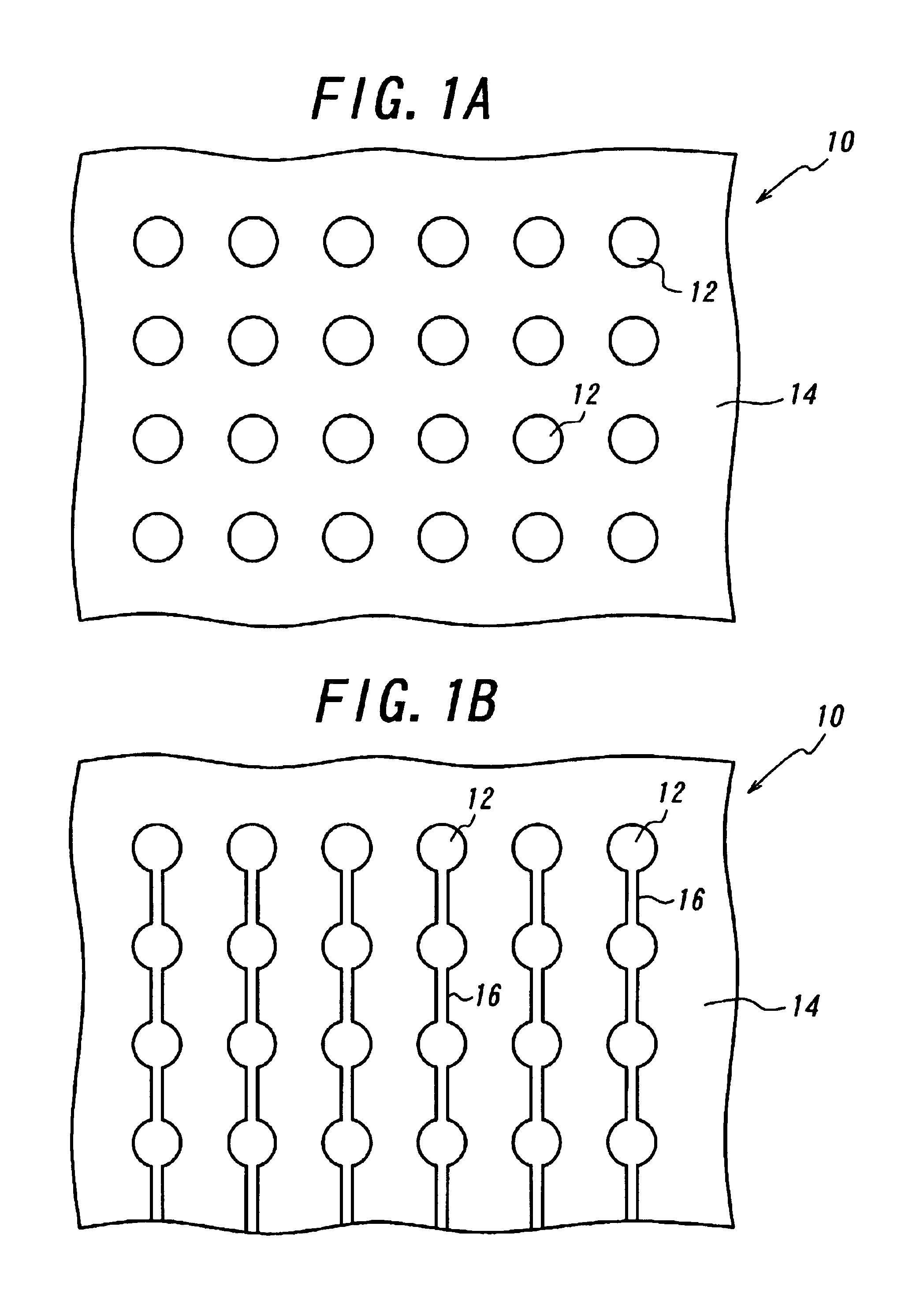
Shown in FIG. 1A is an electrical connector 10 provided with only a plurality of electric contacts 12 on a flexible printed circuit board 14 by way of example. In order to carry out the surface treatment of the electric contacts 12, the electroless plating is preferable for this purpose because power supply lead wires are not required. In practice, however, the electroless plating could not be carried out in this case due to problems such as longer process time and peeling of copper foils as described previously. Consequently, the electrolytic plating must be carried out even if there is a need for electrical connections between the electric contacts 12 as by power supply lead wires 16.

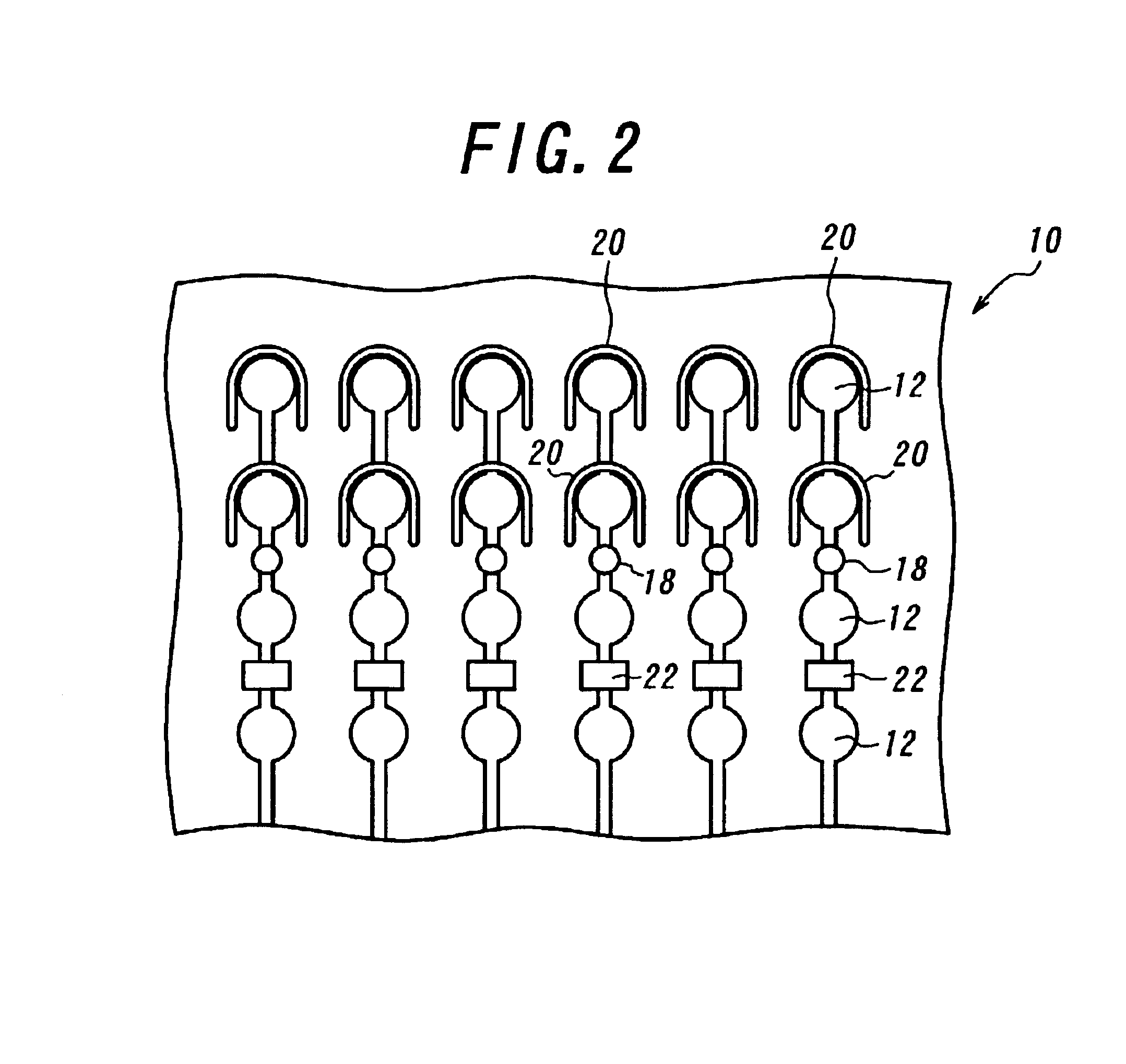
After the electrolytic surface treatment, however, it is required to cut off the electrical connections in order to render the respective electric contacts electrically independent of one another. The electrical connections can be cut off by forming apertures 18, rectangular slits 22 or U-shaped slits...


PUM


Abstract

An electrical connector includes an elastomer layer or board and a plurality of fine lead wires embedded in the elastomer layer and extending rectilinearly therein at right angles to both the surfaces of the elastomer layer. Recesses are formed in the elastomer layer around peripheries of openings of through-holes in which the fine lead wires are embedded. The electrical connector further includes two flexible printed circuit boards on both the sides, each including electric contacts to be connected to mating contacts, connection portions each formed with a through-hole passing therethrough, and conductors each electrically connecting the connection portion to the electric contact. When the flexible printed circuit boards and the fine lead wires are electrically connected by vapor reflow soldering, the flexible printed circuit boards and the elastomer layer having the fine lead wires embedded therein are clamped by restraining jigs to prevent from the flexible printed circuit boards from moving away from the elastomer layer. With this arrangement, reliable connection between the fine lead wires and the flexible printed circuit boards can be achieved without need to control the length of the fine lead wires without any risk of the flexible boards being deflected or warped during soldering even if circumferences of portions to be electrically connected are covered by the insulator.

Description

BACKGROUND OF THE INVENTIONThis invention relates to an electrical connector, and more particularly to an electrical connector having electric contacts on both sides.In order to inspect performance of semiconductor elements of a ball grid array package having a plurality of electric contacts in the form of a hemispherical protrusion made of solder or the like, for example, a socket connector has been used, which is detachably fitted with the ball grid array package. Such a socket connector includes a desired number of electric contacts to be connected to the electric contacts made of solder of the ball grid array package. Some socket connectors have electric contacts of as many as several hundreds in the largest number case. Their electric contacts are arranges with extremely narrow pitches, typically 0.8 mm. Such electric contacts are often arranged on a flexible printed circuit board.As described above, several hundreds, of the electric contacts are arranged with extremely narrow ...

Claims


Application Information

Patent Timeline
IPC IPC(8): H01R13/24H01R13/22H05K3/32H05K3/34H05K3/36
CPCH01R13/2414H05K3/326H01R9/096H05K3/365H05K3/3447H01R12/52
Inventor OHTSUKI, TOMONARIYAMAZAKI, YASUE
Owner THE FUJIKURA CABLE WORKS LTD
Why Eureka
Try Eureka