
Apparatus for applying foamed coating material to a traveling textile substrate

a technology for textile substrates and apparatuses, applied in the field of apparatus for applying foamed coatings to traveling textile substrates, can solve the problems of environmental pollution, insufficient structural integrity of textile substrates, and the need to efficiently apply coating materials, and achieve the effect of easy movement and complete cleaning

Inactive Publication Date: 2005-02-22
GASTON SYST INC
View PDF100 Cites 8 Cited by
  • Summary
  • Abstract
  • Description
  • Claims
  • Application Information

AI Technical Summary

Benefits of technology

The present invention overcomes the drawbacks associated with conventional foam applicators by providing a coater having a foam applicator capable of delivering a metered amount of viscous foamed coating material to a traveling substrate regardless of the structure of the substrate. The applicator of the present invention is moveable between an operating position adjacent a traveling substrate and a flush position adjacent a flush pan. In its operating position, the applicator uniformly delivers a predetermined metered amount of foamed material to a traveling substrate in contact with an open slot of the applicator. Pressure and blow ratio of the foamed coating material are controlled to ensure that the desired amount of coating material is uniformly applied in a way that coating material penetrates at least partially into the interstices of the fabric before the foamed material collapses. The coater of the present invention can be used to deliver different foamed coating compositions; however, it is particularly suited to delivering film-forming coating compositions having a high viscosity, such as latex, because of the coater's ability to accommodate both temporary and long-term line stoppages without allowing significant foam pressure equalization or film formation and associated applicator clogging.
The coater of the present invention accommodates temporary line stoppages by providing a valve assembly in the applicator. The valve assembly has an applicator flow valve member for stopping foam flow to the traveling substrate and a bypass flow valve member for diverting foam flow to a bypass passage that allows foamed coating material to continue moving in the foam delivery system without being applied to the substrate. A foam recirculation path may be established in which foamed material exiting the applicator via the bypass passage is directed by a foam recirculation pump to the foam generator foamer head and then back to the applicator. During such foam recirculation, the supply of fresh coating material and air to the foam generator is stopped. When the line recommences operation, the applicator flow valve member preventing foam flow to the applicator slot is opened and the bypass flow valve member is shut, thereby restoring foam flow to the traveling substrate. When long-term production stops are required, the coater of the present invention may be easily repositioned to a flush position in which the open slot is adjacent a flush pan. In this position, foamed material may be completely flushed from the applicator system into the flush pan.
Advantageously, the applicator of the present invention can be operated while facing downward to accommodate textile production lines having downward-facing traveling fabrics and then the applicator can be flushed while facing generally upward. This upward orientation allows flushing fluid to remain in the applicator after flushing has been completed, thereby preventing film formation on the walls of the applicator by insuring that the walls never dry out.
The present invention also provides a method of flushing a foam coater apparatus wherein a flushing foam is first introduced into the coater and then high velocity flushing fluid is used. This method has been found to flush foamed material from a coater more completely than using only a straight water flush because the flushing foam, having a density more similar to the density of the foamed coating material than the density of the flushing fluid, is more effective in flushing the foamed coating material from the applicator. The use of a flushing foam prevents problems associated with conventional water flushing, such as ineffective foam flushing due to the channeling of the flushing fluid in the foamed coating material within the pipes of the applicator. After flushing the applicator with a flushing foam, a high-velocity water flush may advantageously be conducted.
Using the coater of the present invention, it is therefore possible to obtain the advantages of using foamed coating materials without the disadvantages commonly associated with film-forming materials. The coater of a present invention delivers uniformly a predetermined metered amount of foamed material to a traveling substrate regardless of the substrate structure and regardless of the coating material viscosity. Temporary production stops are no longer a problem because foam flow is maintained in the distribution system and bypassed around the substrate. Recommencing operation is easily achieved by again directing the foamed material through the open slot in the applicator and closing the bypass passage. When coating operations are complete, the coater of the present invention can be easily moved to a flush position and completely cleansed using flushing foam following by a flushing fluid, such as water. The applicator can be left substantially full of flushing fluid in order to prevent film formation along the walls of the applicator before the next coater use. These and other advantages of the present invention will become apparent upon reading the following detailed description and appended claims, and upon reference to the accompanying drawings.

Problems solved by technology

Failure to uniformly apply sufficient coating material to the substrate could result in such deficiencies as insufficient structural integrity of the textile substrate in the case of binder coating processes or inconsistent or variable coloration in the case of a dye coating process.
Second, coating material must be efficiently applied.
Using more coating material than required is wasteful and therefore costly and applying coating materials in an inefficient manner, such as spraying, can result in environmental pollution and necessitate costly measures to reduce the environmental impact of the coating process.
Applying a uniform coating to a textile substrate in an efficient manner is particularly difficult when the coating material is a material such as latex or any other material that is film-forming at atmospheric pressure.
These coating materials typically have higher viscosities than many textile coating materials and can also dry inside coating machinery and thereby clog or reduce the flow in that machinery.
Any film buildup on the walls of the applicator nozzle can either clog the nozzle or result in delivery of less than the designed amount of coating material.
This immersion method, therefore, is inefficient because too much coating material is applied to the substrate and wasteful because some coating material is lost in the subsequent process of removing the excess material.
But absorption and capillary action can result in nonuniform application of coating material, especially when using viscous coating materials such as latex because the effectiveness of these methods depends in large part upon the structure or composition of the substrate.
A non-uniform substrate often results in non-uniform absorption or capillary coating.
While these variations are perhaps more efficient than solely coating a textile fabric, they can also produce such undesirable results as the lack of uniform distribution of coating material and waste of coating material.
But even foamed coating material have disadvantages.
For example, it is often difficult to achieve uniform application of foamed coating material to a substrate because the results of conventional foamed coating methods often vary depending on the structure of the textile substrate or the viscosity of the coating material.
Another problem with conventional foamed coating methods is how to accommodate disruptions or stoppages in the textile processing line.
This difficulty results from the fact that foamed material breaks down over time and becomes nonuniform if pressure is ever allowed to equalize in the distribution path.
When processing of a textile substrate is halted, as would be required to accommodate machine stoppages upstream or downstream of a traveling textile substrate, to correct substrate breakage, or to change substrate materials, then either the foam applicator must be shut—thereby risking equalizing pressure in the foam distribution system—or foam flow can be continued—thereby wasting coating materials and wasting that portion of the traveling substrate upon which the excess coating material accumulates during the line stoppage.
Complicating the problem even further is the fact that many textile mills process fabric face-down.
This procedure allows workers clear visibility of the processes occurring to the back side of the fabric but face-down processing of textile fabrics is problematic for coating machines dispensing film-forming coating material because when the fabric line stops or is shut down there is the risk that the film-forming coating will dry in the applicator nozzle or on the inner surface of the coating delivery piping.
If the coating material is a foamed film-forming material, the problem is worse still because there is the added difficulty of not allowing the foamed material to equalize pressure throughout the distribution line.
But these applicators have not achieved all of the desirable characteristics of a coating apparatus discussed above.
While latex is disclosed as a suitable treating composition, the Walter et al. patent does not appear to specifically address the inherent film-forming problem associated with latex application or a method of cleansing such a film-forming material from the applicator when not in use.
Also, as in the previously discussed patent, the Ashmus patent does not specifically address the problem of film formation during line stoppages or the problems incurred when using the disclosed applicator head in a fabric line to treat fabric face-down.
Such an apparatus would therefore be undesirable for use in applying a film-forming material to a traveling textile substrate that could not withstand applicator pressure without breaking the substrate.
Moreover, this patent does not appear to include latex or other film-forming compositions among the intended treating compositions and thus it too does not address the unique problem associated with such compounds.

Method used


Image

  • Apparatus for applying foamed coating material to a traveling textile substrate
  • Apparatus for applying foamed coating material to a traveling textile substrate
  • Apparatus for applying foamed coating material to a traveling textile substrate

Examples


Embodiment Construction

The present invention will now be described fully hereinafter with reference to the accompanying drawings, in which preferred embodiments of the invention are shown. This invention may, however, be embodied in many different forms and should not be construed as limited to the embodiments set forth herein. Rather, these embodiments are provided so that this disclosure will be thorough and complete, and will fully convey the scope of the invention to those skilled in the art. It will be understood that all alternatives, modifications, and equivalents are intended be included within the spirit and scope of the invention as defined by the appended claims.

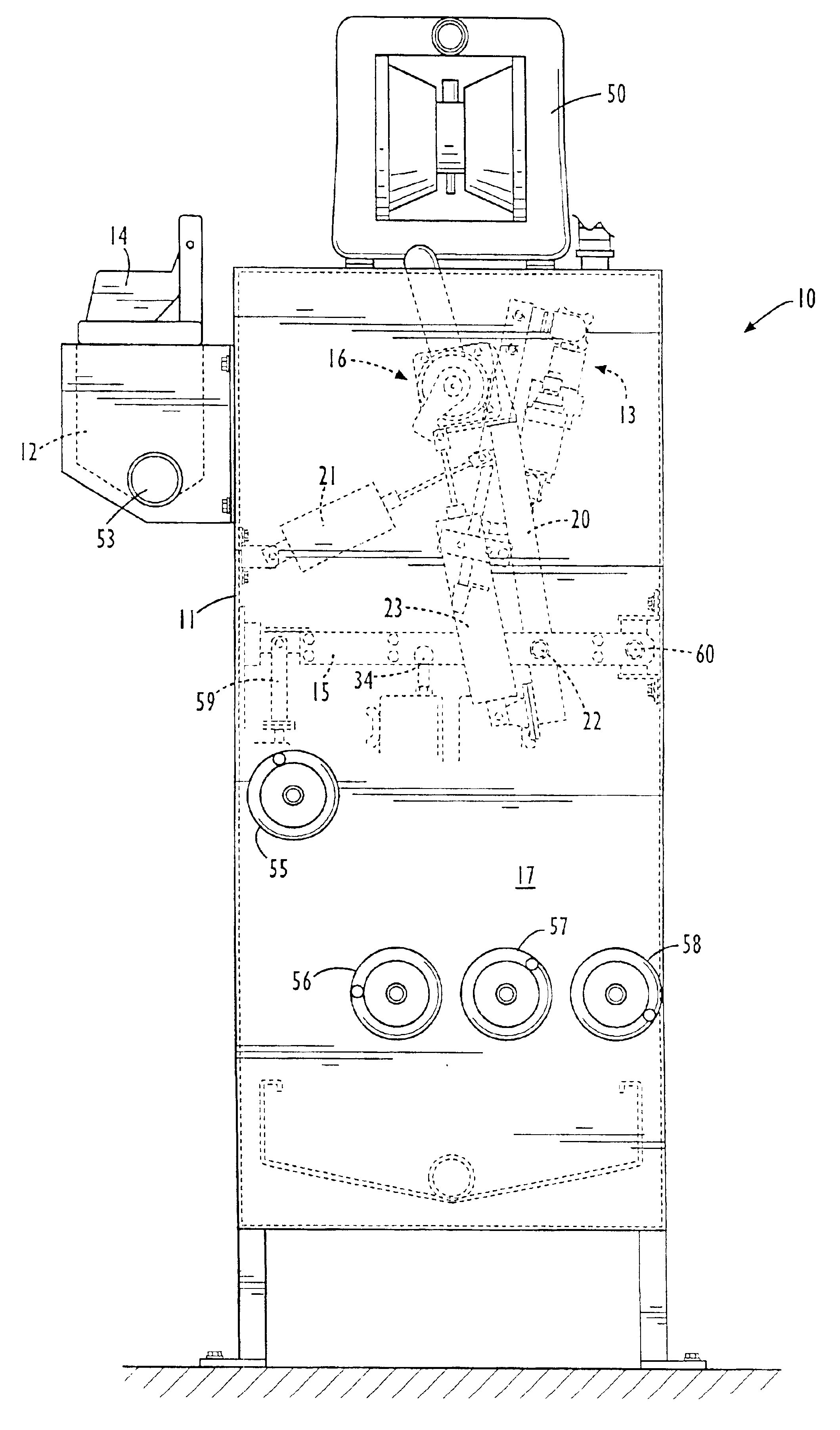
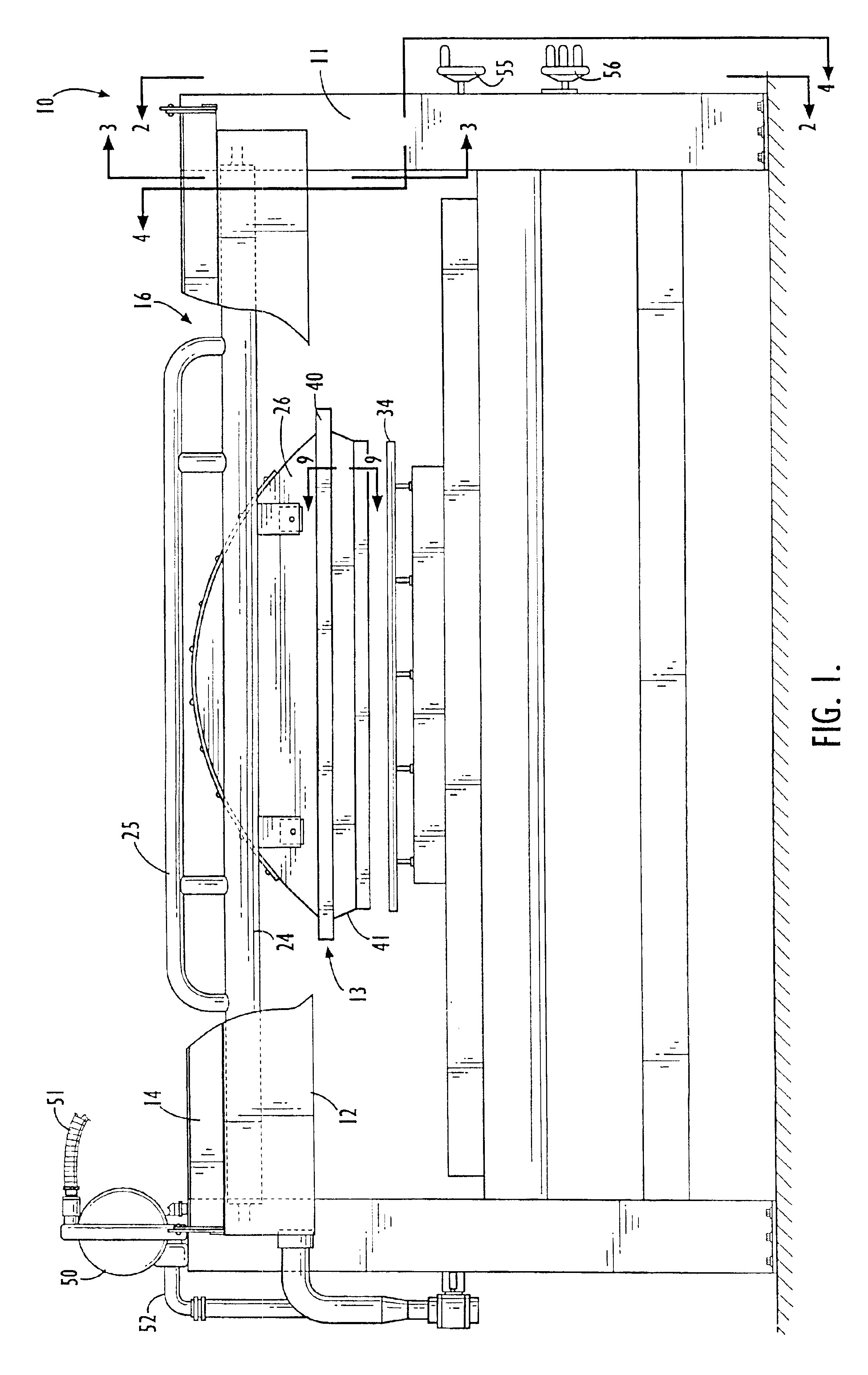
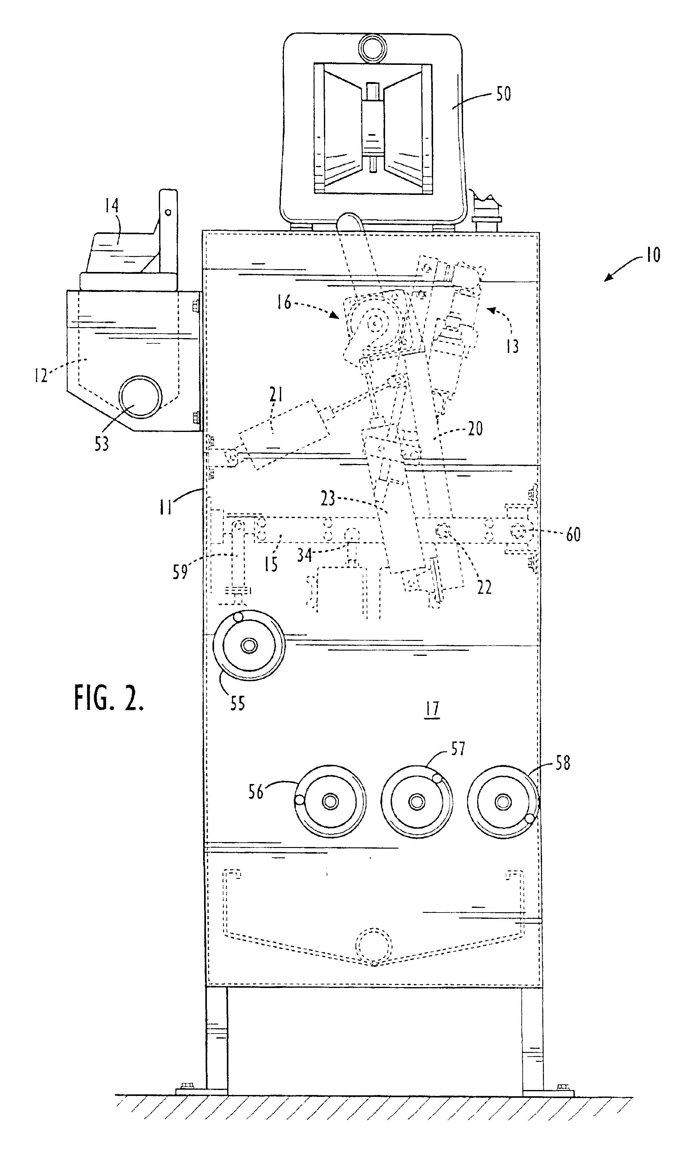
Turning now to FIG. 1, there is shown a coater 10 for applying foamed material to a traveling textile substrate. The coater 10 comprises a frame 11, a flush pan 12 (which is partially cut away in FIG. 1), an applicator 13, and a positioning mechanism 16 moveably mounting the applicator 13 onto the frame 11. The positioning mechanism 16 ...


PUM

PropertyMeasurementUnit
Flow rateaaaaaaaaaa
Viscosityaaaaaaaaaa

Abstract

A coater for applying foamed coating material to a traveling textile substrate including a frame, a flush pan, an applicator having an open slot, a pivot shaft journaled in a pair of support arms that are pivotally mounted to the frame and piston-cylinder mechanisms to move the applicator between an operating position wherein the open slot is adjacent the traveling substrate and a flush position wherein the open slot is adjacent the flush pan by pivoting the support arms and rotating the pivot shaft. Foamed coating material is applied by supporting the traveling substrate between two spaced support elements, contacting the traveling substrate with a foam applicator, and forcing a metered amount of foamed material at least partially into the interstices of the textile substrate before the foamed coating material collapses. A metered amount of foamed coating material is applied onto or into a textile substrate regardless of textile substrate structure and regardless of the viscosity of the coating material. The foamed coating material may be flushed from the coater by stopping flow of foamed material through the applicator, moving the applicator to the flush position, and commencing flow of a flushing fluid through the applicator and into the flush pan. Foamed coating material may also be flushed from the applicator by stopping flow of foamed material through the applicator, commencing flow of a flushing foam through the applicator, stopping flow of flushing foam through the applicator, and commencing flow of a flushing fluid through the applicator.

Description

BACKGROUND OF THE INVENTION1. Technical FieldThis invention relates generally to the field of textile coating machines and more particularly to an apparatus and method for applying a foamed coating to a traveling textile substrate.2. Background InformationThe processing of textile fabrics and similar substrates typically involves application of various coating materials to the fabric to achieve specific purposes. For example, binder coatings are used on some textile substrates to improve the structural integrity of the substrate and dye coatings are often used on textile substrates to achieve a desired fabric color. Regardless of the particular coating being applied, two important and often competing considerations must be addressed. First, it is important that the required amount of coating material be uniformly applied to the textile substrate. Failure to uniformly apply sufficient coating material to the substrate could result in such deficiencies as insufficient structural integ...

Claims


Application Information

Patent Timeline
IPC IPC(8): D06B23/30D06B23/00D06B19/00D06B1/00D06B1/08B05C1/00
CPCD06B1/08D06B23/30D06B19/0094B05C1/00
Inventor ZEIFFER, DIETER F.
Owner GASTON SYST INC
Learn More