
Process for producing fluorinated polyvalent carbonyl compound

a technology of polyvalent carbonyl ester and compound, which is applied in the preparation of halogenated hydrocarbons, carboxylic acid halides, carboxylic compound preparations, etc., can solve the problems of low yield in the reaction for synthesis, high price of perfluoropolyvalent alkyl ester compounds, and limited compounds

Inactive Publication Date: 2005-02-22
ASAHI GLASS CO LTD
View PDF13 Cites 4 Cited by
  • Summary
  • Abstract
  • Description
  • Claims
  • Application Information

AI Technical Summary

Benefits of technology

The present invention has been made in view of the above-mentioned problems of the prior art and is intended to provide a process for producing a fluorinated polyvalent carbonyl compound economically advantageously from materials which are inexpensively available, without requiring a complicated synthetic step.
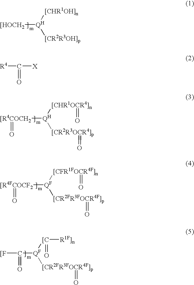
The present inventors have conducted an extensive study to accomplish the above object and as a result, have found it possible to obtain a fluorinated polyvalent carbonyl compound without requiring a complicated synthetic step, by a process wherein a polyvalent alcohol having at least two types of alcohol skeletons among a primary alcohol, a secondary alcohol and a tertiary alcohol, is used as a starting material, and the polyvalent alcohol and an acid halide are reacted to obtain a polyvalent ester compound, which is fluorinated by a specific fluorination method, followed by cleaving the specific ester bonds. Further, it has been found that the above process is an economically advantageous industrial production process, since the polyvalent alcohol is available inexpensively in various structures, and the present invention has been accomplished.

Problems solved by technology

However, in a case where a fluorinated polyvalent carbonyl compound is to be produced by the above prior art method, a polyvalent alkyl ester compound as a raw material for a perfluoropolyvalent alkyl ester compound to be pyrolyzed, is not readily available, and many complicated synthetic process steps will be required, whereby there have been problems such that the price of the perfluoropolyvalent alkyl ester compound is high, and available compounds are rather limited.
Further, the prior art method has had a problem that the yield in the reaction for the synthesis is low.

Method used


Image

  • Process for producing fluorinated polyvalent carbonyl compound
  • Process for producing fluorinated polyvalent carbonyl compound
  • Process for producing fluorinated polyvalent carbonyl compound

Examples


example 1

Example 1-1:

Example for Esterification Step

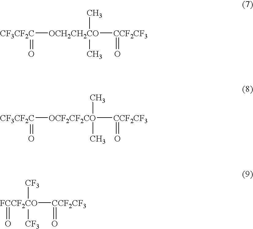
CH2Cl2 (509 g), pyridine (177 g) and HOC(CH3)2CH2CH2OH (20 g) were put into a flask and stirred while bubbling nitrogen gas. CF3CF2COF (72 g) was fed over a period of two hours while maintaining the internal temperature at a level of from −5° C. to +4° C. After completion of the feeding, the reaction crude liquid was dropwise added to a 5 mass % hydrochloric acid aqueous solution (1,400 g) while maintaining the internal temperature at a level of at most 2° C. After liquid separation, washing with a hydrochloric acid aqueous solution was further carried out, followed by liquid separation to obtain an organic layer (500 g). Further, the organic layer was washed with a 5 mass % sodium hydrogencarbonate solution (470 g), and subjected to liquid separation, whereupon the organic layer was washed with water (520 ml) and dried over magnesium sulfate, followed by filtration to obtain a crude liquid (450 g). The crude liquid was concentrated by an e...

example 1-2

Example for Fluorination Step

Into a 200 mL nickel autoclave, R-113 (156 g) was added, stirred and maintained at 25° C. At the gas outlet of the autoclave, a cooler maintained at −10° C. and a pressure controlling bulb were installed in series. Nitrogen gas was supplied for one hour. Then, fluorine gas diluted to 20% by nitrogen gas was supplied at a flow rate of 5.77 L / hr for one hour, and the internal pressure of the reactor was adjusted to 0.15 MPa. Then, diluted fluorine gas was supplied at the same flow rate, and while adjusting the internal pressure of the reactor to 0.15 MPa, a solution obtained by dissolving the compound (7) (4.01 g) obtained in the esterification step, in R-113 (80 g), was injected over a period of 5.8 hours.

Then, diluted fluorine gas was supplied at the same flow rate, and while adjusting the internal pressure of the reactor to 0.15 MPa, a benzene / R-113 solution having a concentration of 0.01 g / mL was injected in an amount of 6 ml while raising the temperat...

example 1-3

Example for Step for Cleavage of Ester Bonds

The compound (8) (0.5 g) obtained in the fluorination step was charged into a flask together with NaF powder (0.02 g) and heated at 100° C. for 3.5 hours and at 120° C. for 2.5 hours, in an oil bath while vigorously stirring. At the upper portion of the flask, a reflux condenser having the temperature adjusted at 20° C. and a gas sampling bag were disposed in series. After cooling, a liquid sample (0.4 g) and a gas sample (0.1 g) were recovered. As a result of the analysis by GC-MS, in the liquid sample, the following compound (9) was confirmed to be the main product, and in the gas sample, CF3CF2COF was confirmed to be the main product. The yield of the compound was obtained by NMR and found to be 44.0%. Further, the NMR spectrum data were as follows.

19F-NMR (376.0 MHz, solvent: CDCl3, standard: CFCl3) δ (ppm): 23.4 (1F), −68.2 (6F), −83.1 (3F), −108.5 (2F), −121.3 (2F).


PUM


Abstract

A fluorinated polyvalent carbonyl compound is produced by an economically advantageous method from inexpensive materials without requiring a complicated synthetic process step. Namely, the present invention comprises reacting a polyvalent alcohol having at least two kinds of alcohol skeletons selected among a primary alcohol, a secondary alcohol and a tertiary alcohol, with an acid halide to obtain a polyvalent ester compound, fluorinating it in a liquid phase to obtain a perfluorinated polyvalent ester compound, and cleaving the ester bonds derived from primary and secondary alcohols in the perfluoropolyvalent ester compound to obtain a fluorinated polyvalent carbonyl compound.

Description

TECHNICAL FIELDThe present invention relates to a process for producing a fluorinated polyvalent carbonyl compound and a novel fluorinated polyvalent carbonyl compound.BACKGROUND ARTA fluorinated carbonyl compound such as an acyl fluoride, a perfluoroketone or a perfluoroester, is a compound highly useful as e.g. an intermediate for preparation of various fluorinated compounds. Especially, a fluorinated polyvalent carbonyl compound having at least two types of structures among the above-mentioned three types of structures, in one molecule, is very useful for the preparation of a fluorinated compound having a plurality of functional groups.A method for obtaining a perfluoroacyl fluoride and a perfluoroketone by fluorinating an acid halide and a ketone having respectively corresponding structures by an electrochemical fluorination method (hereinafter referred to as “an ECF method”), or a method for obtaining them by pyrolyzing the ester bonds in perfluorinated alkyl ester compounds, h...

Claims


Application Information

Patent Timeline
IPC IPC(8): C07C51/58C07C45/00C07C45/41C07C45/54C07C67/307C07C67/287C07C67/29C07C67/297C07C51/60C07C67/14C07C67/00
CPCC07C45/54C07C51/60C07C67/14C07C67/287C07C67/29C07C67/307C07C67/297C07C59/21C07C53/46C07C69/63C07C67/293
Inventor OKAZOE, TAKASHIWATANABE, KUNIOSHIRAKAWA, DAISUKEITO, MASAHIROTATEMATSU, SHIN
Owner ASAHI GLASS CO LTD
Learn More