Fuel cell resuscitation method and apparatus

a fuel cell and apparatus technology, applied in the field of fuel cells, can solve the problem that the fuel cell stack can serve as an uninterruptible power supply, and achieve the effect of increasing the flow rate of oxidant streams and improving performan

Inactive Publication Date: 2005-03-01
BALLARD POWER SYSTEMS
View PDF22 Cites 46 Cited by
  • Summary
  • Abstract
  • Description
  • Claims
  • Application Information

AI Technical Summary

Benefits of technology

In a further aspect, a method of operating a fuel cell system includes temporarily increasing the oxidant stream flow rate through the oxidant passage of the fuel cell stack, at defined time intervals during operation of the stack. This aspect of the method is particularly effective for improving performanc

Problems solved by technology

For example, a fuel cell stack can serve as an uninterruptible power supply for compu

Method used


Image

  • Fuel cell resuscitation method and apparatus
  • Fuel cell resuscitation method and apparatus
  • Fuel cell resuscitation method and apparatus

Examples


Embodiment Construction

In the following description, certain specific details are set forth in order to provide a thorough understanding of various embodiments of the invention. However, one skilled in the art will understand that the invention may be practiced without these details. In other instances, well known structures associated with fuel cells, microcontrollers, sensors, and actuators have not been described in detail to avoid unnecessarily obscuring the descriptions of the embodiments of the invention.

Unless the context requires otherwise, throughout the specification and claims which follow, the word “comprise” and variations thereof, such as “comprises” and “comprising” are to be construed in an open, inclusive sense, that is as “including but not limited to.”

Fuel Cell System Overview

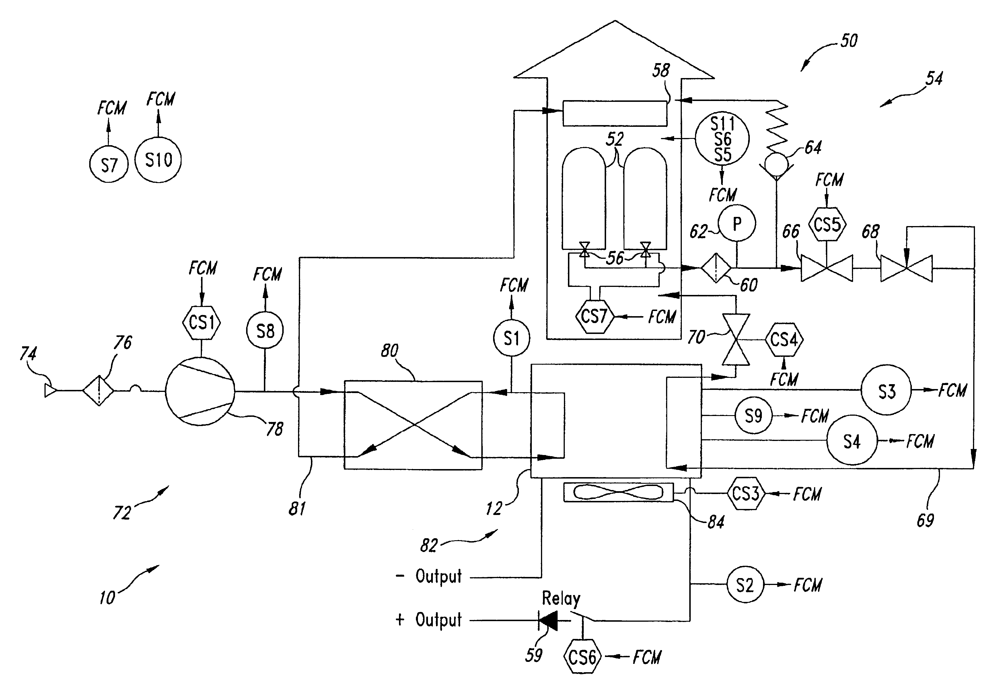
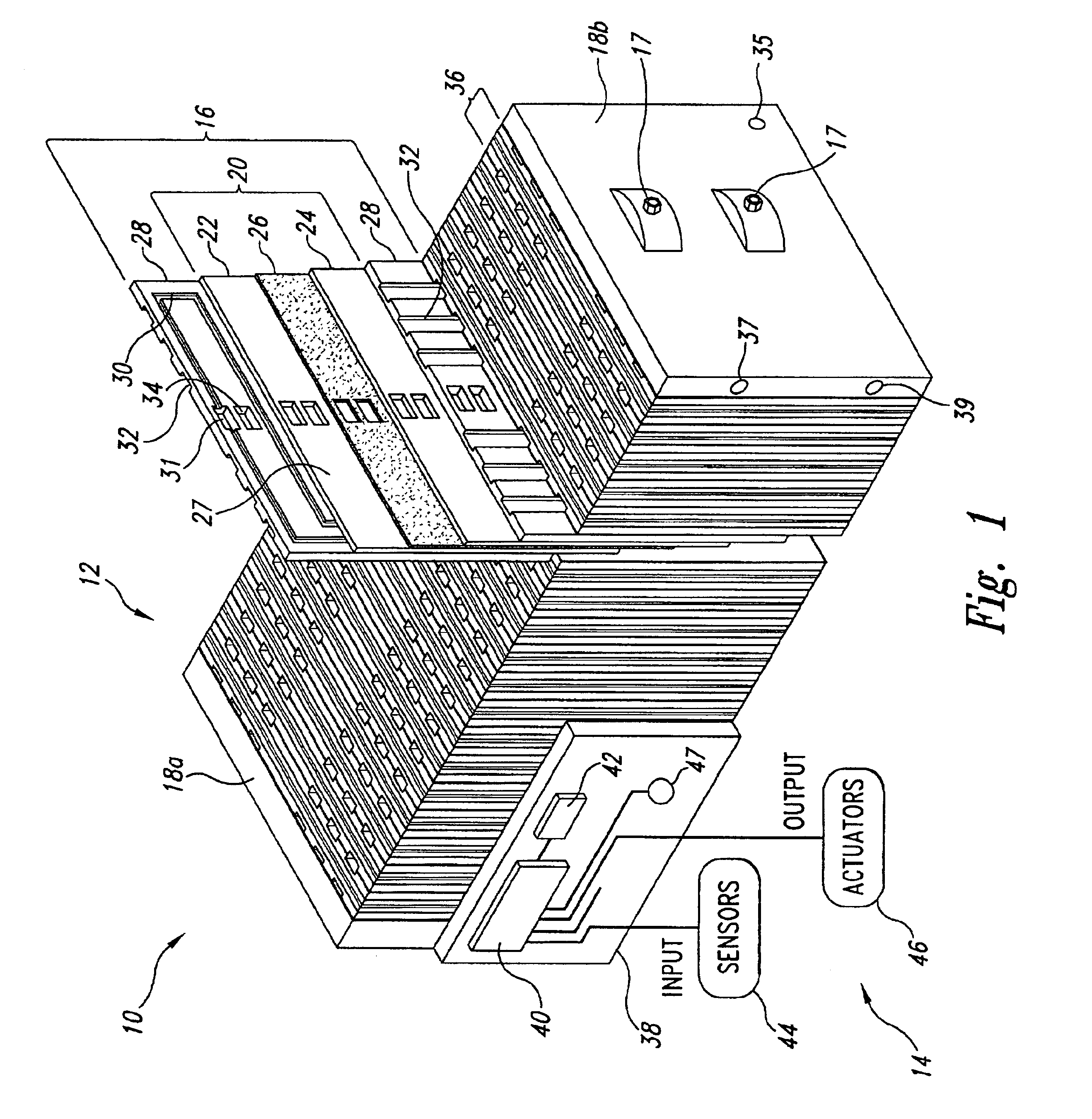
FIG. 1 shows a portion of a fuel cell system 10, namely, a fuel cell stack 12 and an electronic fuel cell monitoring and control system 14. Fuel cell stack 12 includes a number of fuel cell assemblies 16 arranged b...


PUM


Abstract

A fuel cell system includes fuel cells forming a fuel cell stack, having a fuel passage and an oxidant passage. A purge valve is coupled to the fuel passage to exhaust contaminants, and a controller is coupled to temporarily increase the oxidant stream flow rate through the oxidant passage, and to temporarily open the fuel purge valve, if a voltage across a pair of fuel cells is less than a defined threshold voltage. In this resuscitation step, the oxidant flow rate can be temporarily increased by increasing a duty cycle of an air compressor by approximately 50% for a duration of between approximately 5 to 10 seconds. The controller can further shut down fuel cell operation if a voltage across a pair of fuel cells is less than a defined threshold voltage in an inter-resuscitation period immediately following the resuscitation step.

Description

BACKGROUND OF THE INVENTION1. Technical FieldThe present invention relates to fuel cells, and particularly to control systems for fuel cells.2. Description of the Related ArtElectrochemical fuel cells convert fuel and oxidant to electricity. Solid polymer electrochemical fuel cells generally employ a membrane electrode assembly (“MEA”) which comprises an ion exchange membrane or solid polymer electrolyte disposed between two electrodes typically comprising a layer of porous, electrically conductive sheet material, such as carbon fiber paper or carbon cloth. The MEA contains a layer of catalyst, typically in the form of finely comminuted platinum, at each membrane / electrode interface to induce the desired electrochemical reaction. In operation the electrodes are electrically coupled to provide a circuit for conducting electrons between the electrodes through an external circuit. Typically, a number of MEAs are serially coupled electrically to form a fuel cell stack having a desired p...

Claims


Application Information

Patent Timeline
IPC IPC(8): H01M8/04H01M8/10
CPCH01M8/04231Y02E60/50
Inventor WELLS, BRIANUONG, TAN DUCSCHEMBRI, CHARLES JOSEPHJAMES, GREGORY A.SKINNER, GEORGE ALEXANDERGIESECKE, BENNO
Owner BALLARD POWER SYSTEMS
Why Eureka
Try Eureka