Optical component

Inactive Publication Date: 2005-03-08
FUJIFILM HLDG CORP +1
View PDF1 Cites 22 Cited by
  • Summary
  • Abstract
  • Description
  • Claims
  • Application Information

AI Technical Summary

Benefits of technology

Therefore, with the foregoing in mind, it is an object of the present invention to solve the problems of the prior art and to provide an optical component which includes a substrate made of plastic that has light weight, low cost, excellent productivity and a magnesium fluoride film formed thereon as

Problems solved by technology

However, as is well known, a plastic material for an optical component generally does not have sufficient heat resistance to the above-mentioned temperatures, so that it is impossible to form a film with such a high-temperature treatment.
Nonetheless, a product with sufficient characteri

Method used


Image

  • Optical component
  • Optical component
  • Optical component

Examples


first embodiment

First, an optical component of the present invention will be described.

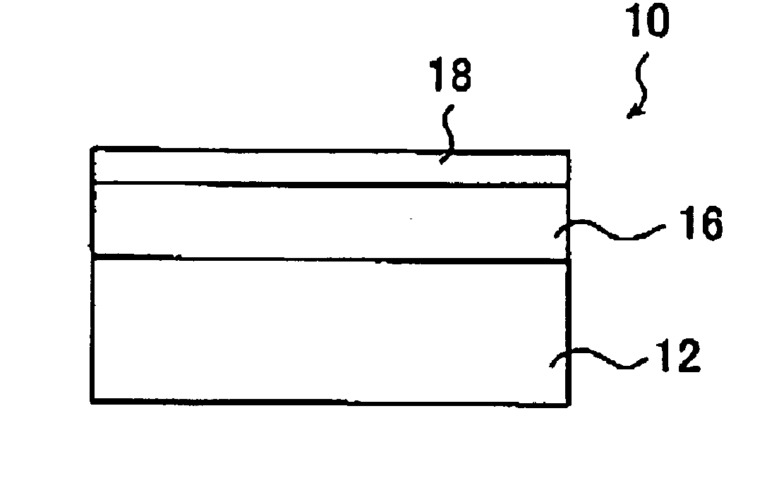
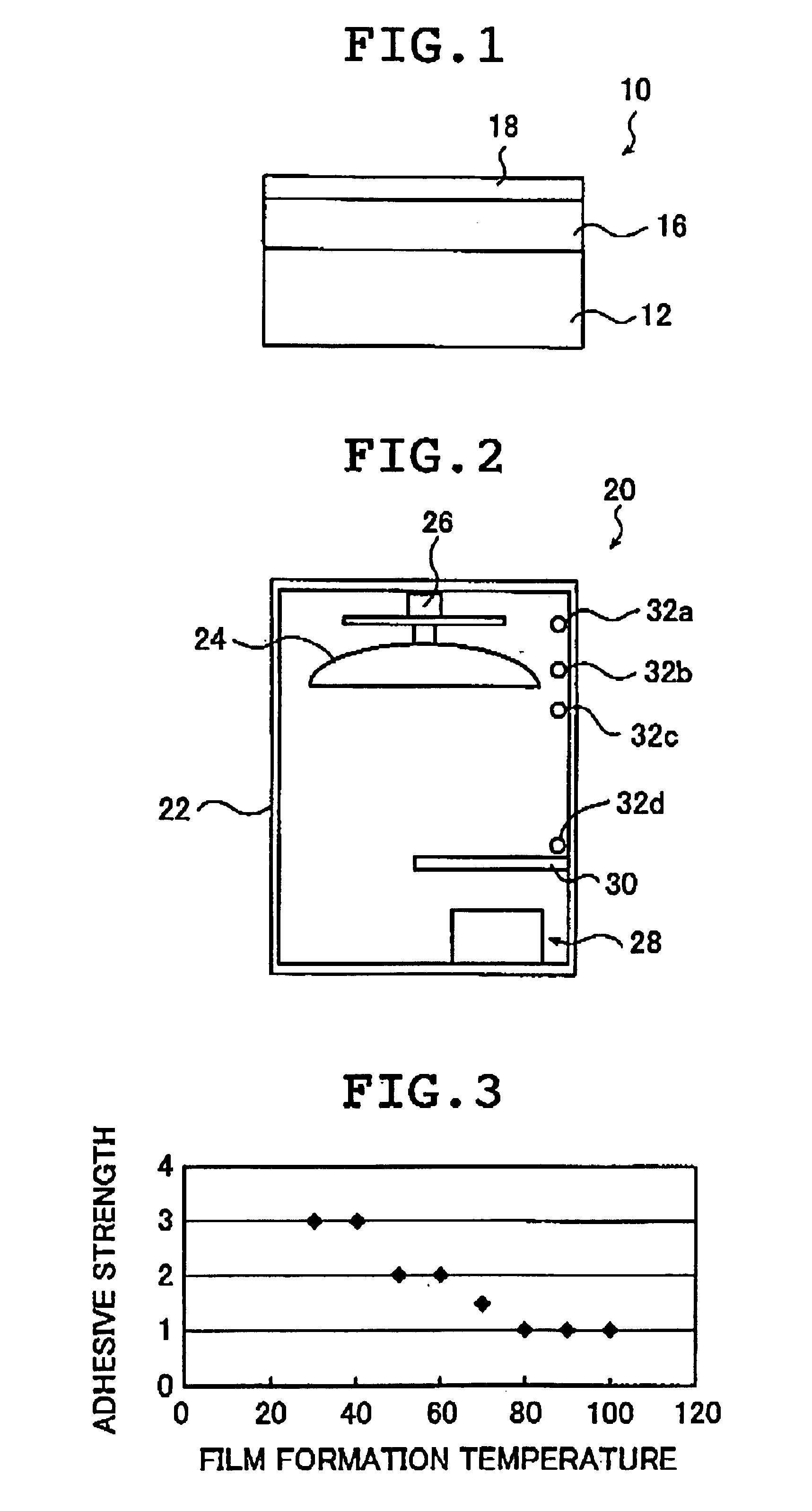
FIG. 1 is a schematic view showing an example of an optical component of the first embodiment of the present invention.

An optical component 10 of the first embodiment of the present invention includes a base member 12 to be a film formation substrate, a magnesium fluoride film 16 (hereinafter, referred to as a “MgF film 16”) formed on the surface of the base member 12, and a silicon oxide film 18 formed on the surface of the magnesium fluoride film 16.

According to the present invention, there is no particular limit to the base member 12, and various known optical components can be used. Examples thereof include various lenses, various filters, various screens, polymer films, optical substrates, and the like.

Furthermore, there is no particular limit to a material for the base member 12, and all the plastics (resin materials) used for optical components can be used. Preferred examples thereof include PMMA (polymeth...

second embodiment

Next, an optical component of the present invention will be described.

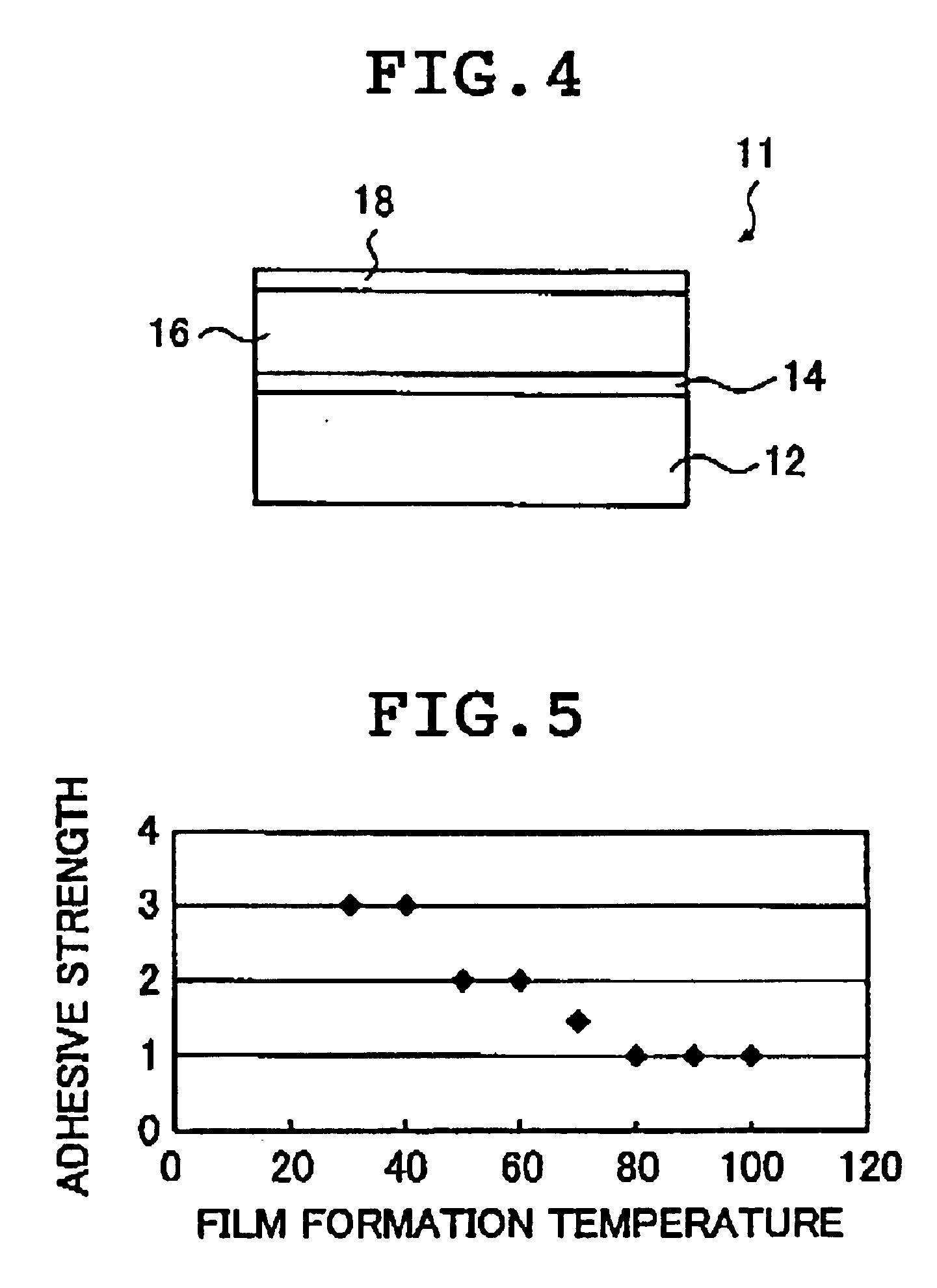
FIG. 4 is a conceptual view showing an example of the optical component of the second embodiment of the present invention.

The optical component 11 of The second embodiment of the present invention includes a base member 12 to be a film formation substrate, a second silicon oxide film 14 formed on the surface of the base member 12, an MgF film 16 formed on the surface of the second silicon oxide film 14, and a first silicon oxide film 18 formed on the surface of the MgF film 16.

The optical component 11 according to the second embodiment of the present invention has a structure and configuration similar to that of the optical component 10 according to the first embodiment of the present invention except that the former has the second silicon oxide film 14 formed between the base member 12 and the MgF film 16. Therefore, like components are identified by like reference numerals and their detailed description will be ...

example 1

First, the specific examples of the optical component 10 according to the first embodiment of the present invention will be described.

Sample No. 1

The MgF film 16 and the silicon oxide film 18 were formed on the base member 12 by using the film formation apparatus 20 shown in FIG. 2, whereby the optical component 10 of the first embodiment of the present invention was produced.

The following operation was performed so that the measurement results by all the temperature measuring units 32 and the temperature measuring unit of the base member 12 became 22° C. to 27° C. from the beginning of melting to the end of film formation of the silicon oxide film 18. Furthermore, an electron gun of 6 kV was placed in the electron gun evaporation source 28.

First, a lens made of PMMA (VH 001, produced by Mitsubishi Rayon Co., Ltd.) was set as the base member 12 at a predetermined position of the rotation dome 24.

Furthermore, a hearth accommodating MgF2 (n=1.35 to 1.4) and a hearth accommodating SiO2...


PUM

PropertyMeasurementUnit
Temperatureaaaaaaaaaa
Thicknessaaaaaaaaaa

Abstract

This optical component includes a film formation substrate made of plastic, a magnesium fluoride film formed at an upper side of the film formation substrate and a first silicon oxide film formed on the magnesium fluoride film. The magnesium fluoride film may be formed on a surface of the film formation substrate. Alternatively, the optical component further may include a second silicon oxide film formed on a surface of the film formation substrate and between the film formation substrate and the magnesium fluoride film. The optical component can be realized, which is excellent in film adhesiveness, mechanical strength, drug resistance, environment resistance, and the like, as well as optical characteristics, and which is also excellent in productivity, film formation operability, cost, and the like.

Description

BACKGROUND OF THE INVENTION1. Field of the InventionThe present invention relates to an optical component such as a lens. More specifically, the present invention relates to an optical component that has satisfactory low light-reflection, and a simple structure with a good outstanding strength, and in addition is excellent in terms of cost and productivity.2. Description of the Related ArtMagnesium fluoride has been widely used as a material for a light reflection preventing film of various optical components such as a lens due to its inexpensiveness and low refractive index.In an optical component, a reflection preventing film made of magnesium fluoride is generally formed on an optical component by vacuum deposition. However, an optical component itself absorbs moisture, so that the following is known: in order to obtain a reflection preventing film with sufficient strength as well as optical characteristics, excluding such an adverse effect, it is required to heat an optical comp...

Claims


Application Information

Patent Timeline
IPC IPC(8): C08J7/06C08J7/00C23C14/06C23C14/10G02B1/11G02B1/10C08J7/043C08J7/046
CPCC08J7/06C23C14/0694C23C14/10G02B1/113Y10T428/265Y10T428/24975Y10T428/24967Y10T428/31938Y10T428/31507Y10T428/31935Y10T428/31667Y10T428/31931C08J7/043C08J7/046
Inventor FUJINAWA, JUNNAKADA, JUNJI
Owner FUJIFILM HLDG CORP
Why Eureka
Try Eureka