

Protective coating for electrolytic capacitors
a technology of electrolytic capacitors and protective coatings, which is applied in the manufacture of electrolytic capacitors, capacitor dielectric layers, electrical apparatus, etc., can solve the problems of increasing leakage current and various problems still remaining with the capacitors formed therefrom, and achieve the effect of low leakage curren
- Summary
- Abstract
- Description
- Claims
- Application Information
AI Technical Summary
Benefits of technology
Problems solved by technology
Method used
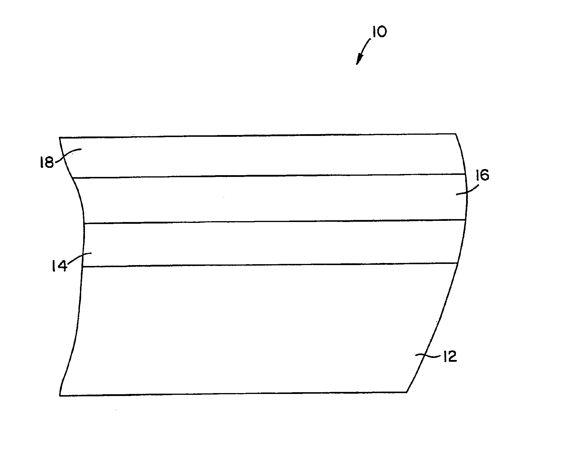
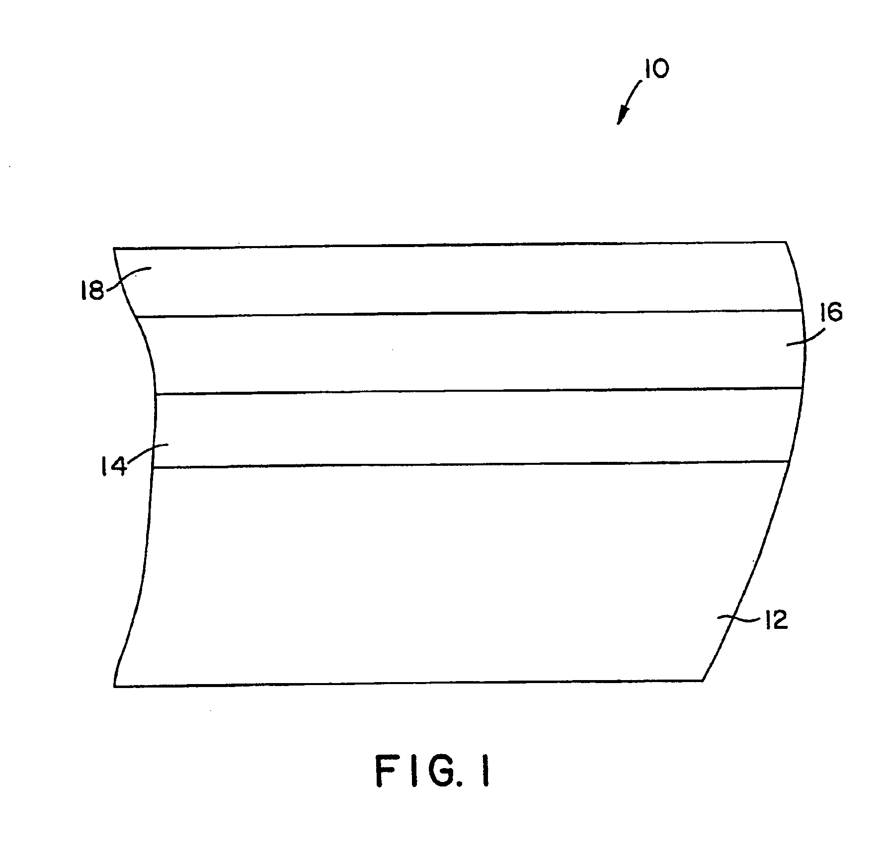
Image


Examples
example 1
The ability of the protective coating of the present invention to form a tantalum capacitor with excellent electrical properties was demonstrated. In particular, eleven 100 μF / 10 V anode parts were formed using the techniques described above. The first six anode parts (Nos. 1-6) were coated with three protective layers by being dipped three consecutive times into a solution of tung oil and di(ethylene glycol) ethyl ether acetate. Further, the remaining five anode parts (Nos. 7-11) were coated with three protective layers by being dipped three consecutive times into a solution of polyurethane and di(ethylene glycol) ethyl ether acetate.
After each individual dip in the protective layer solution, the samples were dried in an oven at 85° C. for 10 minutes and then at 125° C. for an additional 10 minutes. Upon formation of the entire protective coating, the samples were stored overnight to ensure that the protective layers were cured.
Thereafter, each sample was then coated with four laye...
example 2
The ability of the protective coating of the present invention to form a tantalum capacitor with excellent electrical properties was demonstrated. In particular, three sets of ten 1 μF / 10V TAZA anode parts were obtained from the AVX factory in Biddeford, Me.
The anode parts Nos. 1-10 were coated with three protective layers by being dipped three consecutive times into a solution of 0.46 grams polyurethane and 40 milliliters di(ethylene glycol) ethyl ether acetate. The anode parts Nos. 11-20 were coated with three protective layers by being dipped three consecutive times into a solution of 0.46 grams of tung oil and 40 milliliters di(ethylene glycol) ethyl ether acetate. The anode parts Nos. 21-30 were coated with four protective layers by being dipped four consecutive times into a solution of 0.66 grams of shellac and 40 milliliters di(ethylene glycol) ethyl ether acetate.
After each individual dip in the protective layer solution, the samples were dried in an oven at 85° C. for 10 mi...
example 3
The ability of the protective coating of the present invention to form a tantalum capacitor with excellent electrical properties was demonstrated. In particular, the procedure of Example 2 was repeated, except that the anode parts utilized were 4.7 pF / 10V TAZA anode parts obtained from the AVX factory in Biddeford, Me. The median results for each sample are shown below in Table IV.
TABLE IV Electrical Properties of the Samples Coated with Polyurethane, Tung Oil, and Shellac MeasuredDryNormalizedLeakageDry LeakageDryDryCurrentCurrentCapacitanceDf,ESRPart(μA)(μA / μF*V)(μF)(%)(mohms)Polyurethane2170.0 50.1 4.3315.55 262.5Tung Oil0.050.00124.182.14216.5Shellac0.080.00184.451.42236.5
Thus, as indicated above, the samples formed with a protective coating of the present invention exhibited excellent electrical properties. For instance, as shown in Table IV, the median normalized leakage current for the 4.7 μF / 10 V samples made with shellac was 0.0018 microamps / CV, while the medi...
PUM
| Property | Measurement | Unit |
|---|---|---|
| boiling point | aaaaa | aaaaa |
| boiling point | aaaaa | aaaaa |
| boiling point | aaaaa | aaaaa |
Abstract
Description
Claims
Application Information