Digital intermediate frequency receiver module for use in airborne SAR applications

a receiver module and digital intermediate frequency technology, applied in the field of synthetic aperture radar systems, can solve the problems of difficult to find saw filter, and limited pass-band and stop-band performan

Active Publication Date: 2005-03-08
NAT TECH & ENG SOLUTIONS OF SANDIA LLC
View PDF8 Cites 85 Cited by
  • Summary
  • Abstract
  • Description
  • Claims
  • Application Information

AI Technical Summary

Benefits of technology

[0019]In accordance with the unique operable features of the present invention, the IF converter can creates a second IF operating at about a center frequency that is lower than the first IF, the IF converter can adapt the digital receiver for compatibility with the first IF prior to signal processing through the ADC, and the at least one phase history data interface can move data from the digital receiver to real-time image formation processors via a high-speed switched fabric backplane, and to the phase history recorder via a standard front panel data port.

Problems solved by technology

The primary disadvantages of an analog receiver implementation are:The IF filtering is performed in expensive and it is hard to find SAW filters 120 with limited pass-band and stop-band performance,A triple conversion receiver is required due to the need of a 2nd IF frequency to accommodate the SAW filters,The analog quadrature demodulation circuit requires calibration, component screening, tuning, or all of the above to maintain adequate quadrature image rejection,Two balanced ADCs 130 are required, andThe implementation has very little operational flexibility.

Method used


Image

  • Digital intermediate frequency receiver module for use in airborne SAR applications
  • Digital intermediate frequency receiver module for use in airborne SAR applications
  • Digital intermediate frequency receiver module for use in airborne SAR applications

Examples


Embodiment Construction

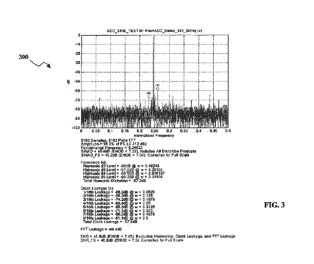
ator / filter output cases: one with broadband noise dither, and the other with band-limited noise at the ADC input.

[0028]FIG. 7: Simplified block diagram of the DRX DSP chain.

[0029]FIG. 8: Simplified demodulator / filter with two demultiplexed inputs.

[0030]FIG. 9: Fully parallel demodulator / filter with input demultiplexer.

[0031]FIG. 10: Sample output PSD plots for the 74-tap demodulator / filter for a sine wave in noise, wherein the left plot is the Simulink / System Generator simulation; the right plot is the DRX hardware implementation.

[0032]FIG. 11: Block diagram of the pane filter.

[0033]FIG. 12: Comparison of a 9.5 MHz bandwidth SAW filter to the 20 pane FIR filter with D=22.

[0034]FIG. 13: IF bandwidth vs. radar operating range. and

[0035]FIG. 14: Frequency response for two azimuth prefilter (APF) examples.

DETAILED DESCRIPTION OF PREFERRED EMBODIMENTS

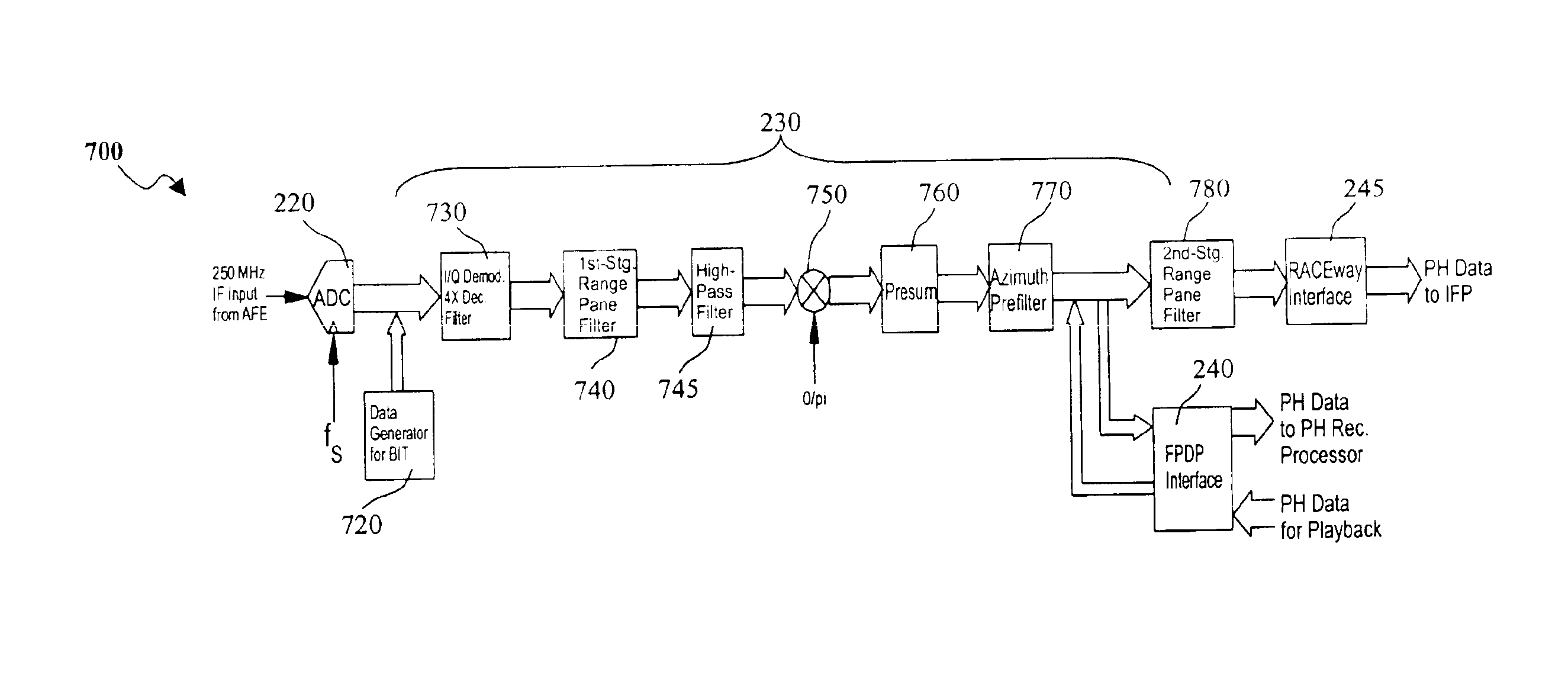
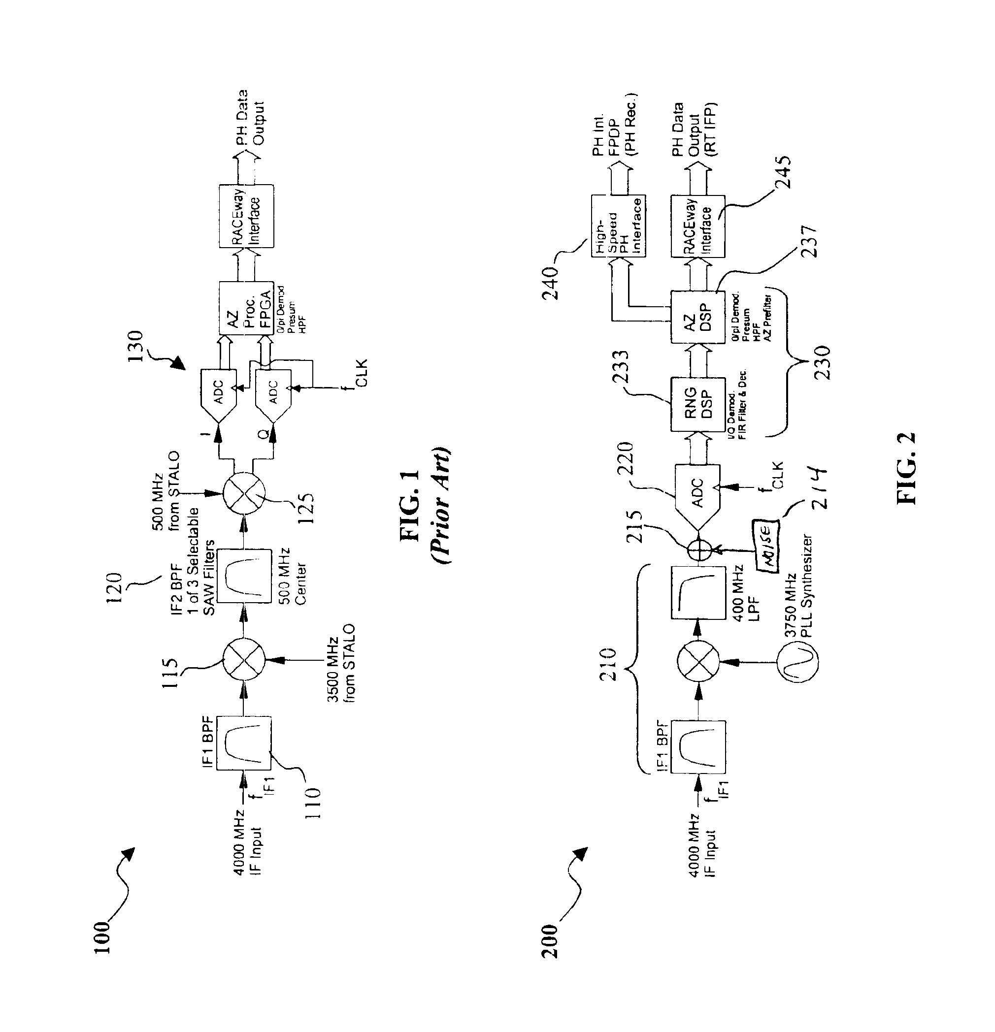
[0036]Referring to FIG. 2, a simplified block diagram of the digital receiver (DRX) module 200 useful in accordance with the present inven...


PUM


Abstract

A digital IF receiver (DRX) module directly compatible with advanced radar systems such as synthetic aperture radar (SAR) systems. The DRX can combine a 1 G-Sample/sec 8-bit ADC with high-speed digital signal processor, such as high gate-count FPGA technology or ASICs to realize a wideband IF receiver. DSP operations implemented in the DRX can include quadrature demodulation and multi-rate, variable-bandwidth IF filtering. Pulse-to-pulse (Doppler domain) filtering can also be implemented in the form of a presummer (accumulator) and an azimuth prefilter. An out of band noise source can be employed to provide a dither signal to the ADC, and later be removed by digital signal processing. Both the range and Doppler domain filtering operations can be implemented using a unique pane architecture which allows on-the-fly selection of the filter decimation factor, and hence, the filter bandwidth. The DRX module can include a standard VME-64 interface for control, status, and programming. An interface can provide phase history data to the real-time image formation processors. A third front-panel data port (FPDP) interface can send wide bandwidth, raw phase histories to a real-time phase history recorder for ground processing.

Description

GOVERNMENT INTEREST[0002]The present invention was developed under a contract with the United States Department of Energy under contract DE-AC04-94AL85000. Therefore, the U.S. Government has rights to use of the present invention.FIELD OF THE INVENTION[0003]The present invention is generally related to synthetic aperture radar systems. More particularly, the present invention is related to radar receiver modules. The present invention is also related to digital intermediate frequency receiver modules and their use in radar applications.BACKGROUND[0004]Fine-resolution, high-performance synthetic aperture radar (SAR) system having real-time image formation capabilities are currently being developed. For example, a system being developed by Sandia National Laboratories has a 4 GHz first intermediate frequency (IF) receiver. A simplified block diagram of the current generation IF receiver is shown in FIG. 1 which has been labeled as prior art.[0005]The first IF is currently translated i...

Claims


Application Information

Patent Timeline
Patent Type & Authority Patents(United States)
IPC IPC(8): G01S13/90G01S13/00
CPCG01S13/90G01S7/288
Inventor TISE, BERTICE L.DUBBERT, DALE F.
Owner NAT TECH & ENG SOLUTIONS OF SANDIA LLC
Why Eureka
Try Eureka