[0013]One object of the invention is to provide a zoom system for an illumination device that will allow setting a wide range of adjustable degrees of coherence without need for interchanging optical components. It is another object to provide a zoom system providing a highly uniform
energy distribution at its exit end, combined with narrow edge widths and
high transmission, due to the telecentricity of its exit end.
[0018]
Zoom systems in accordance with the invention allow achieving widely varying degrees of coherence, σ, of the light supplied by illumination systems due to their designs alone, where moving lenses of the zoom system allows switching, preferably continuously, between virtually totally coherent
radiation (low values of σ) and virtually totally incoherent
radiation (high values of σ), where the end points of the accessible range of σ may be altered by varying the
divergence angle of the
radiation incident on the zoom system. That
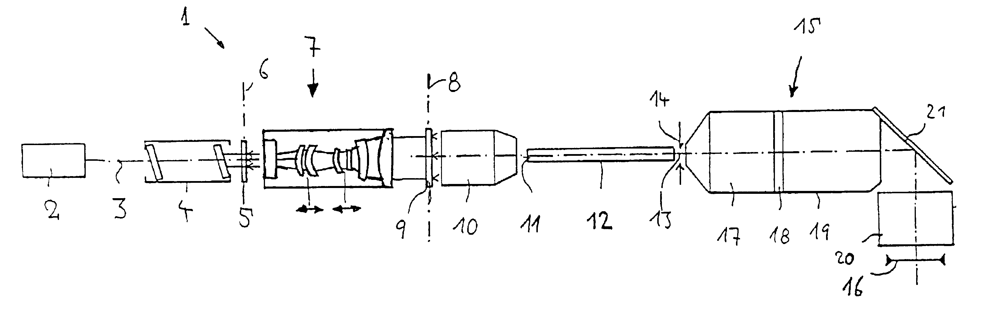
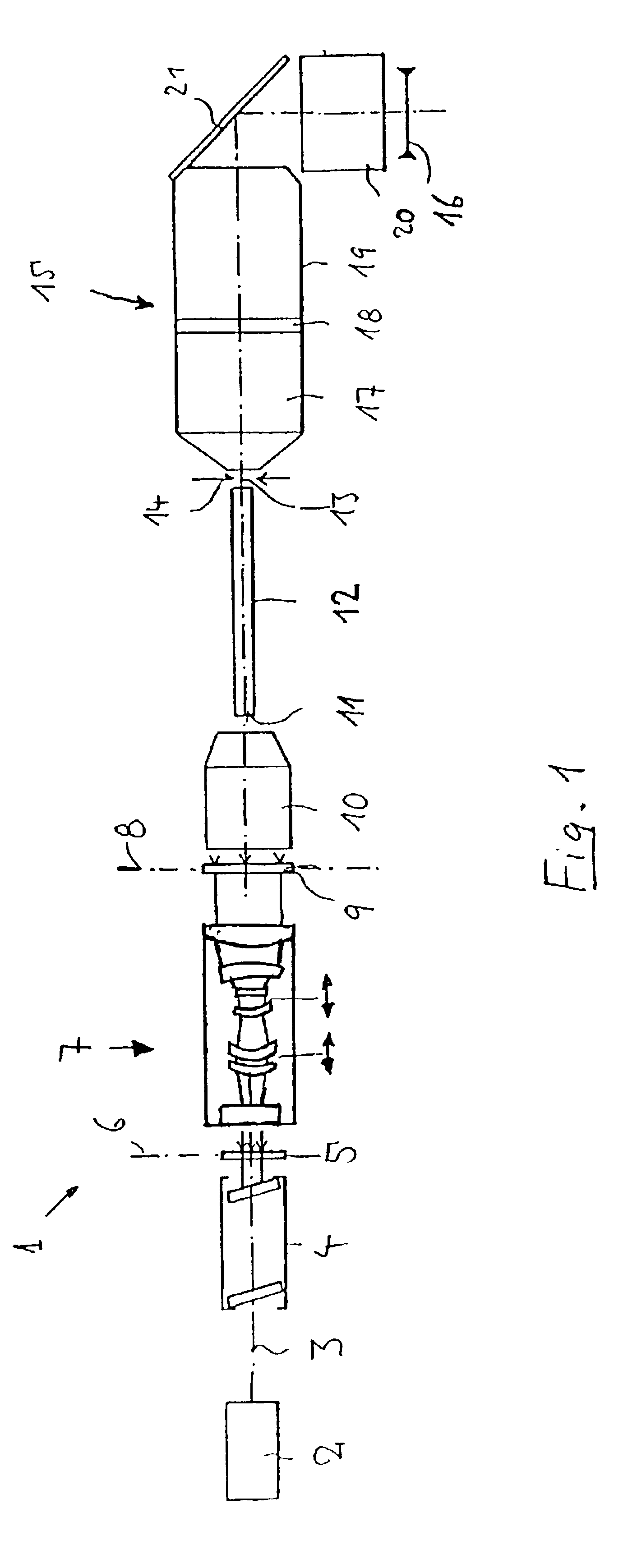
divergence angle may be set by employing, for example, optical means, for example, a graticular, diffractive, optical element, for creating a desired angular luminous-intensity distribution from incident, collimated, light that precede the zoom system in the optical
train. Since the zoom system itself covers a wide range of expansion ratios, or a wide range of σ's, in most applications, a single angular luminous-intensity distribution at its entrance end may be employed for all illumination settings. No interchangeable graticular optical elements or similar will then be required, which greatly simplifies the overall
layout of illumination devices.
[0020]In order to keep the overall length of the entire system short, and, in particular, largely unchanged compared to those of earlier systems, in
spite of the large moving ranges, preferred embodiments have fixed lenses arranged in the vicinity of their object plane and, with some restrictions, in the vicinity of their
image plane as well. A distance between the object plane and the optical element of the zoom system that is closest to the object plane may, preferably, be less than 15%, in particular, even less than 5%, of the overall length of the zoom system, which will also allow a moving range of at least one movable lens to terminate at a distance from the object plane that is less than 15%, in particular, less than 5%, of the overall length of the zoom system. On the image end of the zoom system, the moving range of at least one movable lens may terminate at a distance from the image plane that is less than 50%, in particular, less than 35%, of the overall length of the
zoom lens, which will allow devising a zoom system having
optics that may be employed for making both angular corrections and spatial corrections, regardless of the zoom setting, i.e., of the axial positions of movable lenses.
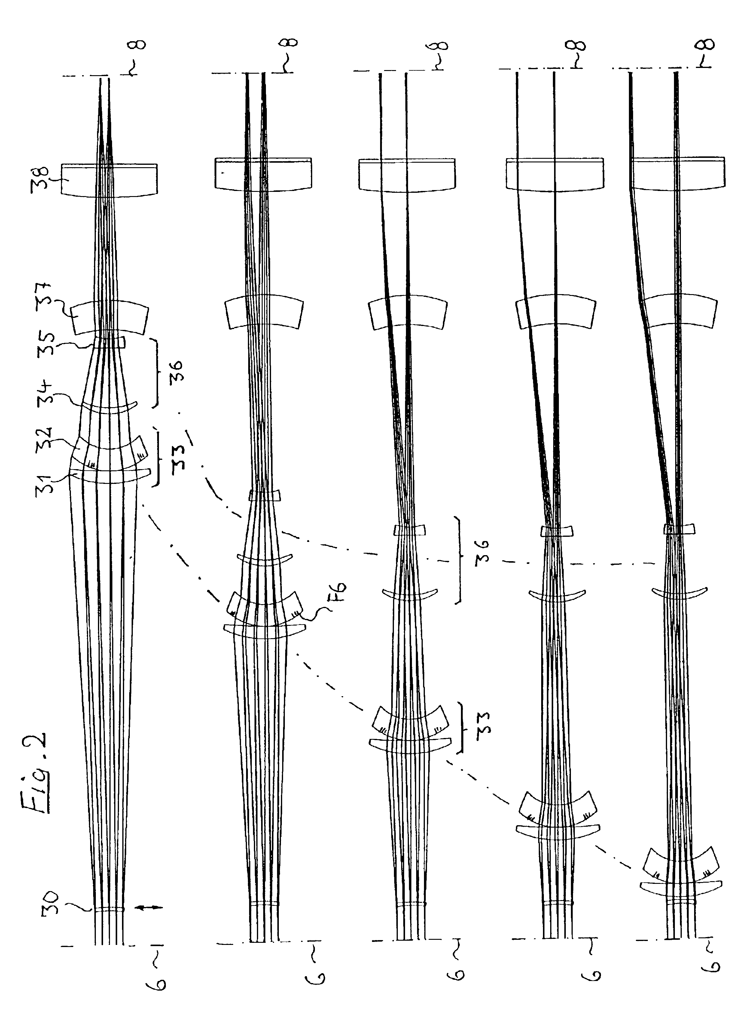
[0021]In order to allow large moving ranges while employing the least possible total number of lenses, it will be preferable to minimize the total number of fixed lenses. In the case of preferred embodiments, the total number of movable lenses is equal to, or greater than, the total number of fixed lenses. For example, three fixed lenses and four movable lenses may be provided. Employing movable lenses that encompass at least one lens group consisting of two or more jointly movable lenses has proven favorable. Every such movable lens group preferably consists of at least two singlet lenses, which will simplify correcting beam paths and reduce angles of incidence. A maximum of two movable lenses or lens groups should preferably be employed in order to keep the mechanical designs of the components required for moving lenses simple. In order to obtain a large
expansion ratio, in
spite of the small number of movable lenses or lens groups, a first movable lens or lens groups and at least a second movable lens or lens group that are movable along differing moving curves when switching between differing zooming positions may be provided, which may be achieved by, for example, employing independent drives or a suitable
nonlinear coupling.
[0022]Preferred embodiments have at least one optical component having at least one aspherical surface arranged between the object plane and image plane. It will be particularly beneficial if at least one aspherical surface is arranged on a movable optical element, which will allow varying the corrective effect of the aspherical element over a broad range whenever necessary. Under some circumstances, employing aspherical optical elements may allow minimizing the total number of system surfaces required. Having a small number of system surfaces is particularly favorable at short operating wavelengths, such as 193 nm, 157 nm, or 126 nm, since the transmission losses in the
optical materials, such as
calcium fluoride, that are available increase with decreasing
wavelength due to increasing absorption and the effectiveness of optical coatings decreases with decreasing
wavelength, while degradation effects increase at shorter wavelengths. Preferred systems have no more than eight lenses, and preferably have just seven or fewer lenses. Arranging at least one aspherical surface in the zoom system also provides benefits in terms of better system performance in that the figure(s) of the aspherical surface(s) may be used to improve, e.g., the uniformity of the (top-head) intensity distribution over the illuminated area, the steepness of the falloff in intensity at the edges of the illuminated area, and the image-end telecentricity of the zoom system.

