One
advantage of the present invention over the prior art lies in the exploitation of
integrated optics for the
interconnection of the photonic components. Specifically, the splitters, directional couplers, and waveguides of the present invention are all integrated on a common substrate and located close to each other. As mentioned earlier, the theoretically predicted
phase noise is the sum of the phase
noise due to the RF-oscillator and the phase
noise incurred by the
injection locking process. As a result, by integrating the components, environmental disturbances such as mechanical vibrations and temperature changes which cause degradations to the amplitude stability and phase noise of the synthesized RF-signal are common to all components, which helps reduce the phase and amplitude
instability. Also, because the waveguides to / from the slave lasers are formed on a common substrate and in proximity to each other, the
relative phase-drifts between the above components is reduced. Therefore, we can expect long term
differential phase stability in the optical injection inputs supplied to the first and second slave lasers. In addition, the two optical signals (the slave
laser outputs) to be heterodyned are combined in a common
waveguide inside the integrated optical
chip. The prior art combines the optical signals using discrete components interconnected by
optical fiber, which decreases
phase stability.
over the prior art lies in the exploitation of
integrated optics for the
interconnection of the photonic components. Specifically, the splitters, directional couplers, and waveguides of the present invention are all integrated on a common substrate and located close to each other. As mentioned earlier, the theoretically predicted phase noise is the sum of the phase noise due to the RF-oscillator and the phase noise incurred by the
injection locking process. As a result, by integrating the components, environmental disturbances such as mechanical vibrations and temperature changes which cause degradations to the amplitude stability and phase noise of the synthesized RF-signal are common to all components, which helps reduce the phase and amplitude instability. Also, because the waveguides to / from the slave lasers are formed on a common substrate and in proximity to each other, the
relative phase-drifts between the above components is reduced. Therefore, we can expect long term
differential phase stability in the optical injection inputs supplied to the first and second slave lasers. In addition, the two optical signals (the slave
laser outputs) to be heterodyned are combined in a common
waveguide inside the integrated optical
chip. The prior art combines the optical signals using discrete components interconnected by
optical fiber, which decreases phase stability.
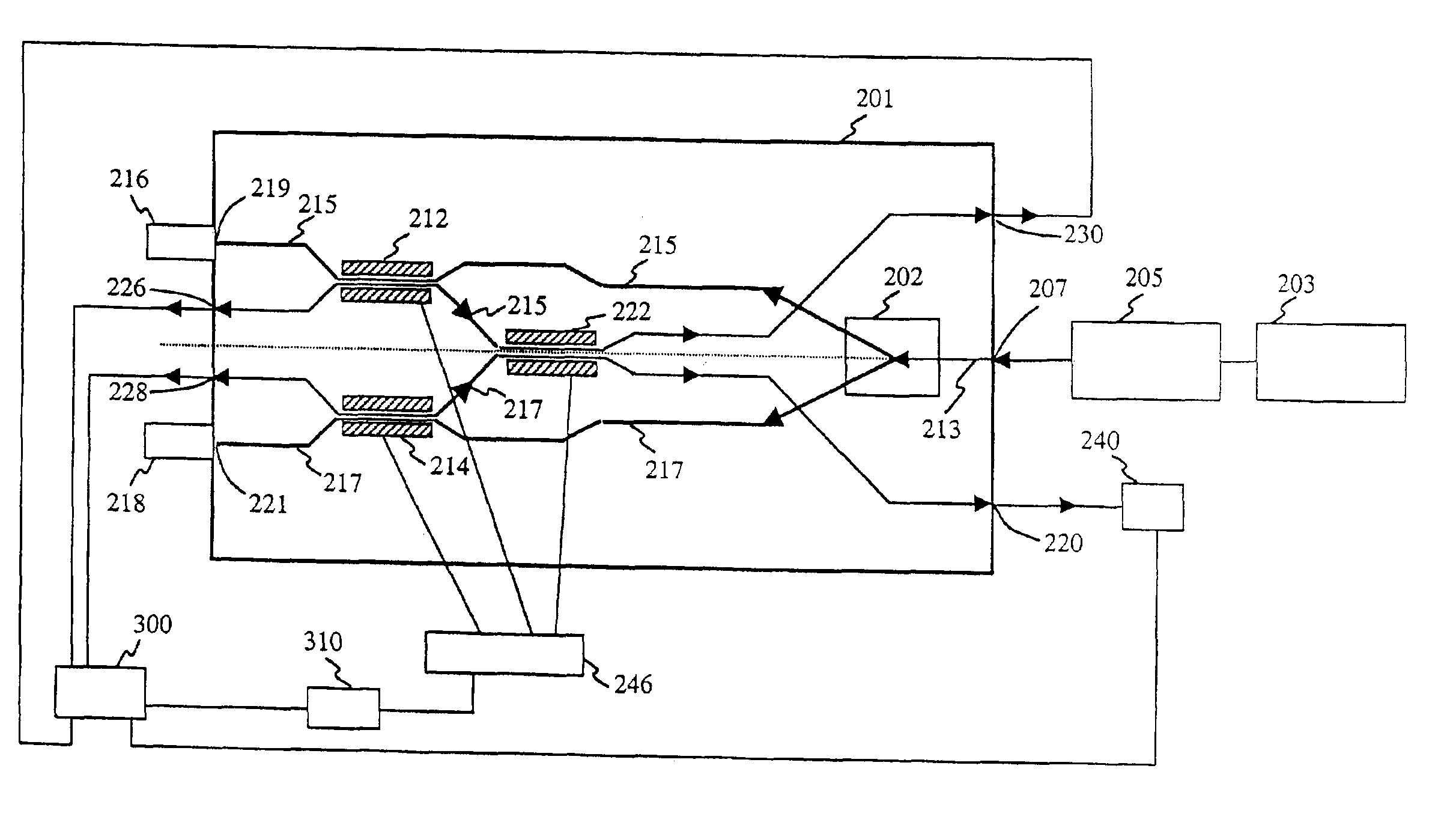
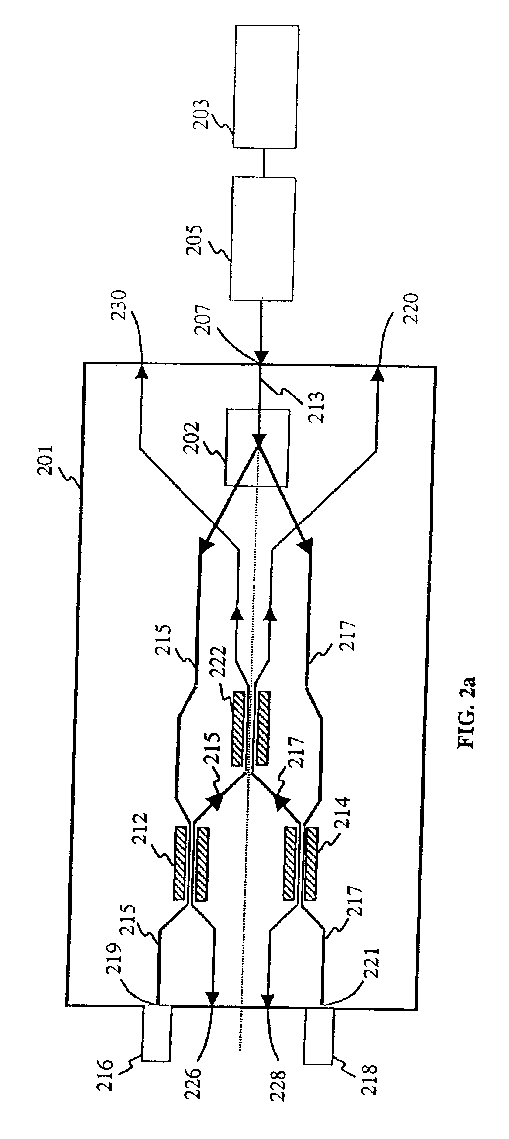
It is therefore an object of the present invention to provide an integrated optical circuit. The integrated optical circuit is formed on a single substrate, receives an
optical comb preferably generated from a mode-locked master
laser, and transfers the
optical comb to a first and a second slave laser, using a first and a second
waveguide path, and a plurality of optical couplers. The first and second slave lasers produce first and second laser outputs which are coupled to an
optical coupler using the first and second waveguide paths. The
optical coupler combines the first laser output and the second laser output creating at least one combined optical output. The combined optical output is then preferably sent to a primary or secondary output port where the combined optical output can be used for heterodyning.
It is also an object of this invention to use optical couplers instead of Mach-Zender modulators and
optical circulators. The optical couplers are preferably 2×2directional couplers. The use of directional couplers, which have 4 inputs / outputs, provides the integrated optical circuit of this invention with
monitoring and control output ports located on the substrate that can be used to monitor chosen characteristics and to implement external control circuits which enhance the performance of the integrated optical circuit.
The directional couplers of this invention as aforementioned, are preferably 2×2 directional couplers, but other optical couplers such as X-junction couplers, or
multimode interference couplers could be used as well. The 2×2 directional couplers have two ports on each side of the directional coupler, which can be used as either an input or an output for light. Furthermore each port is not bound to remain as an input or an output permanently. Each port has the ability to function as both an input and an output, depending on whether light is entering or exiting the port. If light enters the port, it is acting as an input, and when light exits the same port, the port is acting as an output. In this way, a 2×2 directional coupler has 4 inputs and 4 outputs, or any combination thereof. A 2×2 directional coupler is well known in the art. However, bi-directional coupler use of a 2×2 directional coupler in which a given port is used as both an input and an output is not a matter of normal routine.
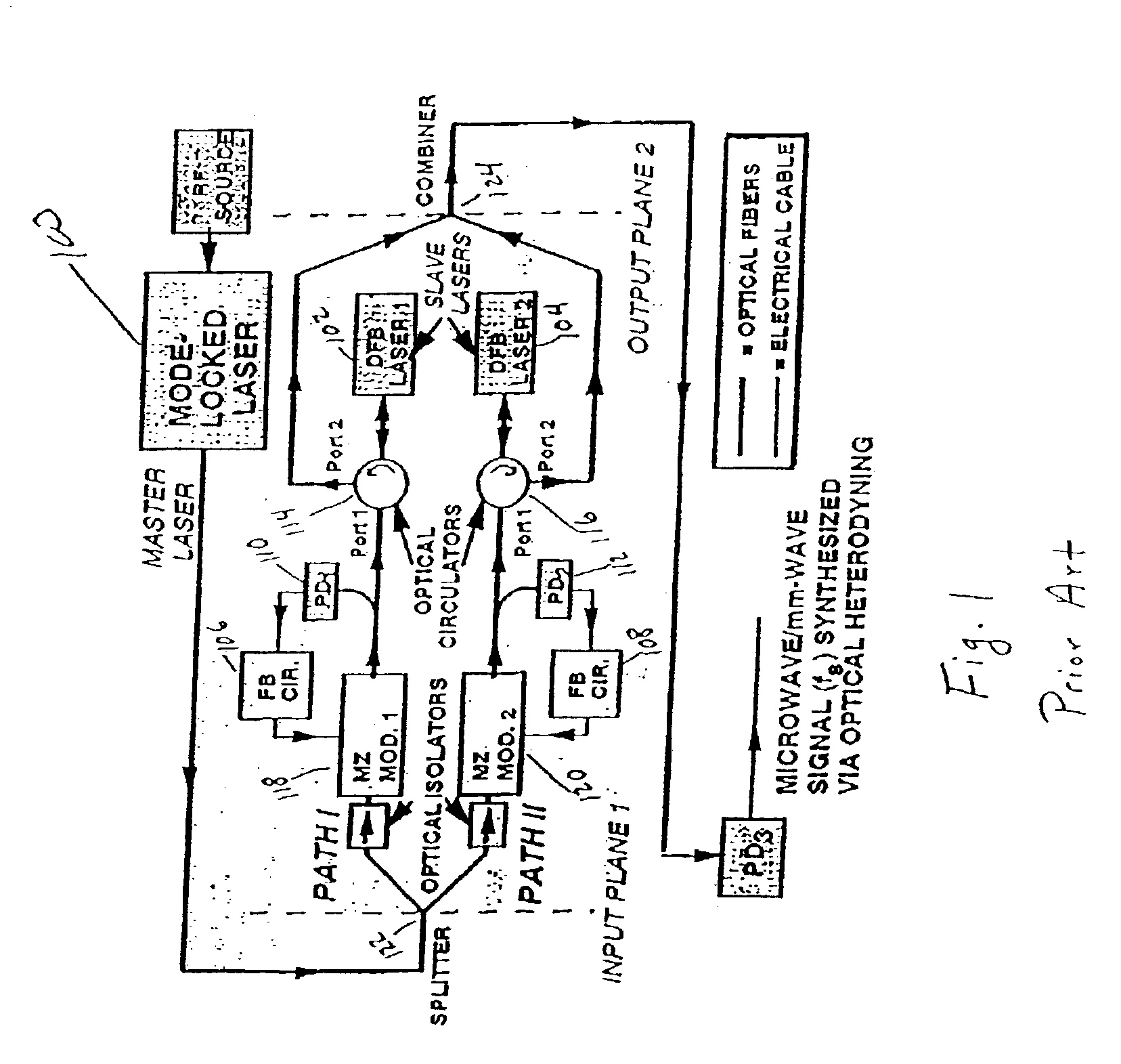
It is also an object of the present invention to provide optical waveguides having substantially shortened lengths. One problem associated with optical heterodyning, which this invention solves, is that as the length of the
optical path increases, the phase stability decreases. The prior art as mentioned earlier, uses components that are pigtailed and connected with lengths of optical
fiber. It is very likely that when implementing the prior art circuit, it will have lengths of optical-
fiber paths that are on the order of meters to 10s of meters long. This is a problem because as mentioned earlier, when the
optical path length increases the phase stability decreases. By integrating the components on an integrated optical circuit, it is possible to reduce the
optical path length to a length in the range of 6-20 centimeters. This difference in optical path lengths using discrete components and integrating the components is roughly a factor of 100. In addition, it is difficult to integrate all of the components of the prior art circuit on a common substrate. The
optical circulators of the prior art are generally bulky items and are especially difficult to integrate.

