Method and apparatus for recovering a clock signal from an asynchronous data signal

a clock signal and data signal technology, applied in the field of system and method for recovering asynchronous digital data by a receiver, can solve the problems of data loss, inability to implement a clock signal having the necessary 4 frequency in an ic, and inability to achieve high frequency signals. practical and cost-effective design

Inactive Publication Date: 2005-03-15
PANASONIC CORP
View PDF6 Cites 19 Cited by
  • Summary
  • Abstract
  • Description
  • Claims
  • Application Information

AI Technical Summary

Benefits of technology

[0009]In an effort to solve the aforementioned needs, it is an object of the present invention to provide a simple, cost effective design for producing a clock signal corresponding to an asynchronous data signal that provides for minimal data loss prior to synchronization between the clock signal and the incoming data signal, and that does require a sampling source having a frequency rate greater than the incoming data signal.
[0011]As described in further detail below, the present invention provides significant advantages over the prior art. Most importantly, the clock recovery system of the present invention provides a simple and cost effective design for the generation of a clock signal corresponding to an asynchronous data signal that minimizes the amount of data lost during the synchronization process. In other words, the clock signal is synchronized to the incoming data signal in minimal time.
[0012]Another advantage is that the system of the present invention does not require the oversampling of the incoming asynchronous data signal. As a result, the present invention eliminates the cost and noise problems associated with the inclusion of an additional oscillator. In addition, as oversampling is not necessary, there are no constraints on the maximum allowable data rate. For example, if 4× oversampling was necessary, the maximum data rate would be ¼ the maximum possible clock rate.

Problems solved by technology

During this “synchronization” period incoming data cannot be recovered, and therefore the data is lost.
However, while such an approach is acceptable for low frequency signals, it is not a practical solution for high frequency signals (e.g., 500 Mbit / sec. signal).
In particular, it is not practical to implement a clock having the necessary 4× frequency in an IC.
Moreover, such a high frequency clock source introduces undesirable noise problems into the circuit.

Method used


Image

  • Method and apparatus for recovering a clock signal from an asynchronous data signal
  • Method and apparatus for recovering a clock signal from an asynchronous data signal
  • Method and apparatus for recovering a clock signal from an asynchronous data signal

Examples


fourth embodiment

[0037]FIG. 21 is an exemplary embodiment of the barrel shifter unit utilized in the present invention.

[0038]FIG. 22 is an exemplary embodiment of the multiplexer 541t utilized in the fourth embodiment of the present invention.

[0039]FIG. 23 is an exemplary embodiment of a latch circuit utilized in the fourth embodiment of the present invention.

[0040]FIG. 24 illustrates an exemplary embodiment of an error detection circuit utilized in the fourth embodiment of the present invention

[0041]FIGS. 25a-25g are exemplary timing diagrams illustrating the operation of the fourth embodiment of the present invention.

[0042]FIG. 26 is a timing diagram illustrating one of the problems solved by the fourth embodiment of the present invention.

DETAILED DESCRIPTION OF THE INVENTION

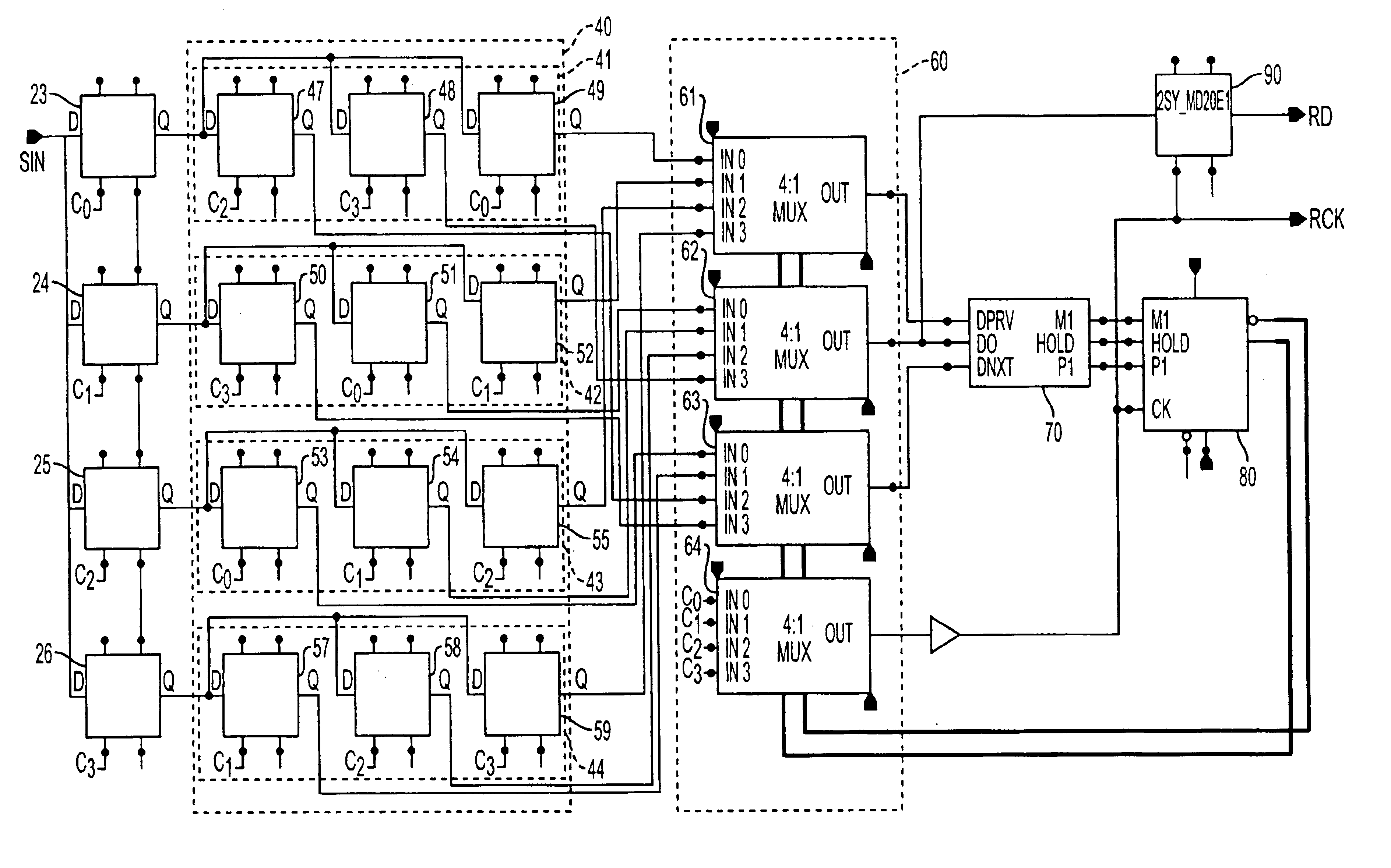
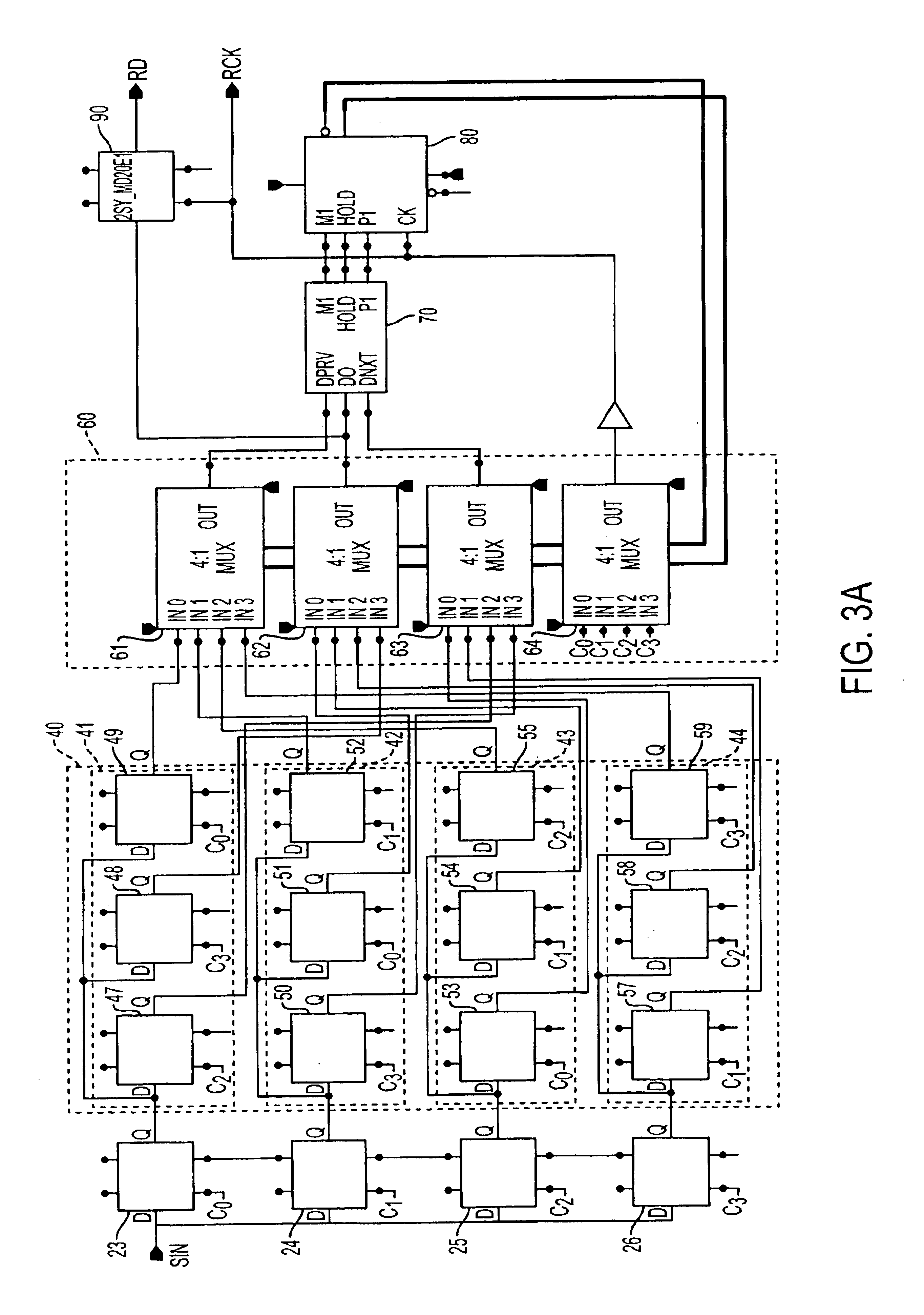
[0043]FIG. 3a illustrates an exemplary embodiment of the clock recovery system of the present invention. As shown, the system 100 comprises a multi-phase sampling unit 22, which comprises four latches (e.g., d-type flip-flops)...

first embodiment

[0074]The output of each of the four phase decoders 111-114 is generated in accordance with the table illustrated in FIG. 5. Thus, each individual phase decoder 111-114 contained in the phase decoder 110 functions in the same manner as the phase decoder described in conjunction with the As shown, the outputs of the first phase decoder 111, M1, Hold and P1 are coupled to the IN0 inputs of multiplexes 121, 122 and 123, respectively, which are contained in the multiplexer circuit 120. Similarly, the outputs of the second phase decoder 112, M1, Hold and P1 are coupled to the IN1 inputs of multiplexes 121, 122 and 123, respectively. The outputs of the third phase decoder 113, M1, Hold and P1 are coupled to the IN2 inputs of multiplexes 121, 122 and 123, respectively. Finally, the outputs of the fourth phase decoder 114, M1, Hold and P1 are coupled to the IN3 inputs of multiplexes 121, 122 and 123, respectively. The outputs of multiplexers 121, 122, 123, are coupled to the M1, Hold, P1 i...

second embodiment

[0075]Thus, in accordance with the operation of the second embodiment, the decoded results of the comparison of samples q0, q1 and q2 are coupled to the barrel shifter 80 by selecting IN0 inputs of the multiplexers 121-123. The decoded results of the comparison of samples q1, q2 and q3 are coupled to the barrel shifter 80 by selecting IN1 inputs of the multiplexers 121-123. The decoded results of the comparison of samples q2, q3 and q0 are coupled to the barrel shifter 80 by selecting IN2 inputs of the multiplexers 121-123. Finally, the decoded results of the comparison of samples q3, q0 and q1 are coupled to the barrel shifter 80 by selecting IN3 inputs of the multiplexers 121-123.

[0076]The multiplexer circuit 120 of the second embodiment further comprises an additional two multiplexers 123 and 125. Multiplexer 124 receives samples q1c0, q2c1, q3c2 and q0c3 at input lines IN0, IN1, IN2 and IN3, respectively. The output of multiplexer 124, which is controlled by the barrel shifter 8...


PUM


Abstract

A clock recovery unit for generating a clock signal corresponding to an asynchronous data signal. The clock recovery unit includes an input port for receiving an incoming data signal; a local oscillator circuit for generating a plurality of clock signals having the same frequency, where the plurality of clock signals are each shifted in phase relative to one another; a sampling unit having a plurality of latches, each of which is clocked by one of the plurality of clock signals generated by the local oscillator circuit, the sampling unit outputting a plurality data samples of the incoming data signal; a data phase alignment unit coupled to the sampling unit, the data phase alignment unit receiving the plurality of data samples as input signals and operative for shifting the phase of the plurality of data samples; a multiplexer circuit coupled to the data phase alignment unit, the multiplexer circuit having a first multiplexer operative for selecting a portion of the plurality of data samples, each of the data samples having a corresponding clock signal, which is one of the plurality of clock signals generated by the local oscillator circuit, the multiplexer circuit having a second multiplexer operative for selecting one of the plurality of clock signals generated by the local oscillator circuit; a phase decoder coupled to the multiplexer circuit, the phase decoder operative for receiving the portion of the plurality of data samples selected by the multiplexer and for generating an output signal indicative of the logic values of the portion of the plurality of the data samples selected by the first multiplexer; and a barrel shifter circuit coupled to the phase decoder, the barrel shifter operative for adjusting the data samples selected by the first multiplexer in accordance with the output signal of the phase decoder.

Description

FIELD OF THE INVENTION[0002]The present invention relates to systems and methods for the recovery of asynchronous digital data by a receiver, and more particularly to an apparatus and method for generating a clock signal corresponding to the asynchronous digital data signal.BACKGROUND OF THE INVENTION[0003]In digital data transmission systems operating in an asynchronous data transfer mode, digital data is output by a transmission unit as an asynchronous serial data signal, without an clock signal embedded therein. Upon reception of the asynchronous serial data signal, the receiver must function to recover the data transmitted by the transmission unit, and to generate a clock signal corresponding to the received data. Importantly, both the generated clock signal and the data must be synchronous (i.e., phase aligned) with one another so as to allow the receiver to properly process the received data.[0004]FIG. 1 illustrates an example of a prior art clock and data regeneration portion...

Claims


Application Information

Patent Timeline
Patent Type & Authority Patents(United States)
IPC IPC(8): H03L7/091H03L7/08H04L7/033
CPCH04L7/0337H03L7/091
Inventor YOSHIZAKI, SHOICHI
Owner PANASONIC CORP
Why Eureka
Try Eureka