Sludge digestion methods and apparatus

Inactive Publication Date: 2005-03-22
BRENTWOOD INDS
View PDF1 Cites 73 Cited by
  • Summary
  • Abstract
  • Description
  • Claims
  • Application Information

AI Technical Summary

Benefits of technology

The digester can also comprise a liquid outlet for discharging liquid continuously from the interior of the vessel. This liquid outlet can, for example, be in fluid communication with an decant weir having an opening disposed at or near the upper surface of the liquid in the vessel, for withdrawing liquid from at or near the upper surface of the liquid and delivering the withdrawn liquid to the liquid outlet. The decant weir can be fixed in the interior of the vessel, whereby the decant weir maintains a maximum liquid depth in the vessel. Alternatively, the decant weir can be vertically movably disposed in the interior of the vessel with respect to the lower surface of the vessel so that various liquid depths may be maintained within the vessel. One or more baffles can be interposed between the distal end of the tube and the liquid outlet, in order to inhibit withdrawal from the vessel of solids suspended in the liquid

Problems solved by technology

Discharge of these materials (many of which exert biological oxygen demand {BOD} when discharged) into the environment with the wastewater can have undesirable health and environmental consequences.
Sludges often have strong odor and contain toxic or infectious agents.
As a result, wastewater sludge is often treated to degrade odiferous, infectious, or toxic components.
Sludge disposal can represent one of the greatest expenses and most cumbersome steps associated with wastewater treatment.
Aerobic sludge digesters also convert sludge to carbon dioxide, water, and inorganic salts, but without significant production of methane.
However, because aerobic digesters require mixing and aeration of the reactor contents, their construction and their operating and maintenance costs can be higher than anaerobic digesters.
Also, the physical layout of aerobic sludge digestio

Method used


Image

  • Sludge digestion methods and apparatus
  • Sludge digestion methods and apparatus
  • Sludge digestion methods and apparatus

Examples


Embodiment Construction

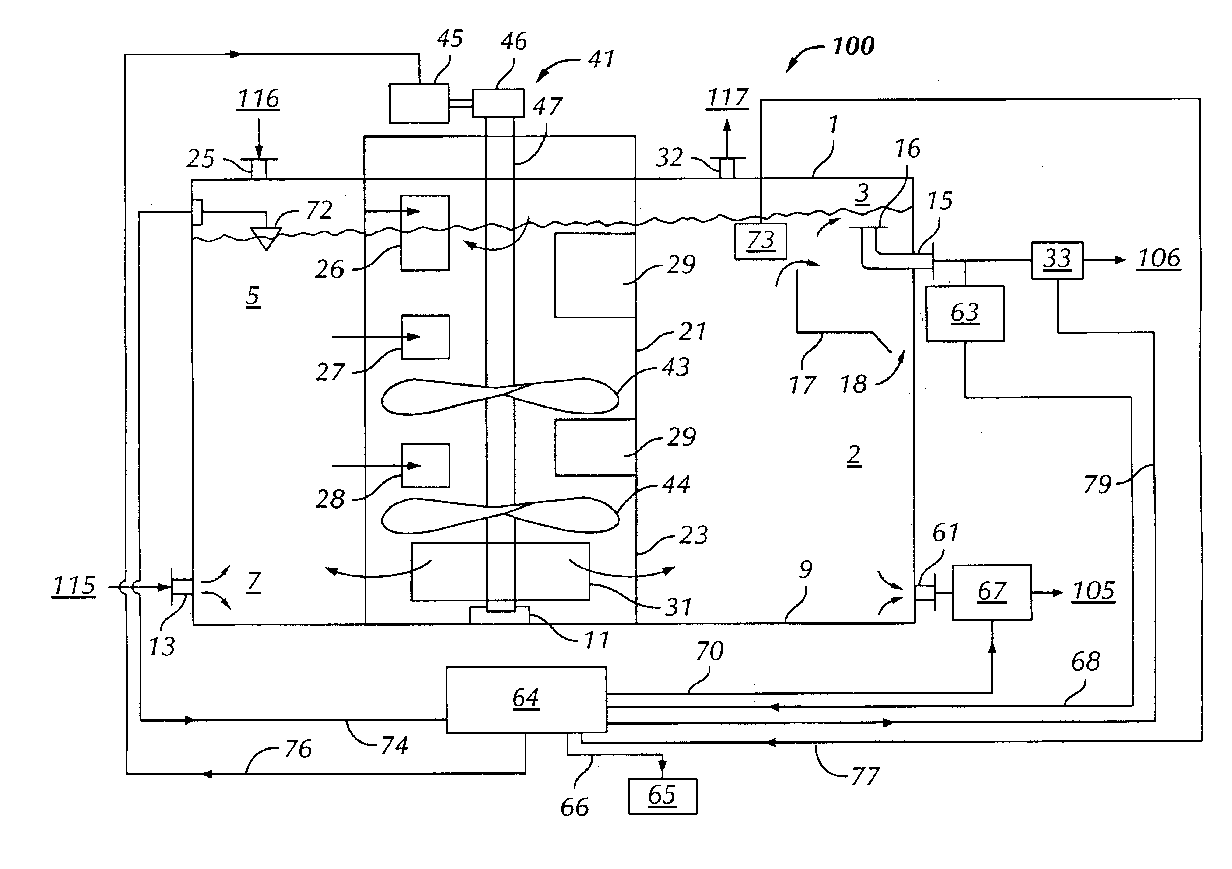
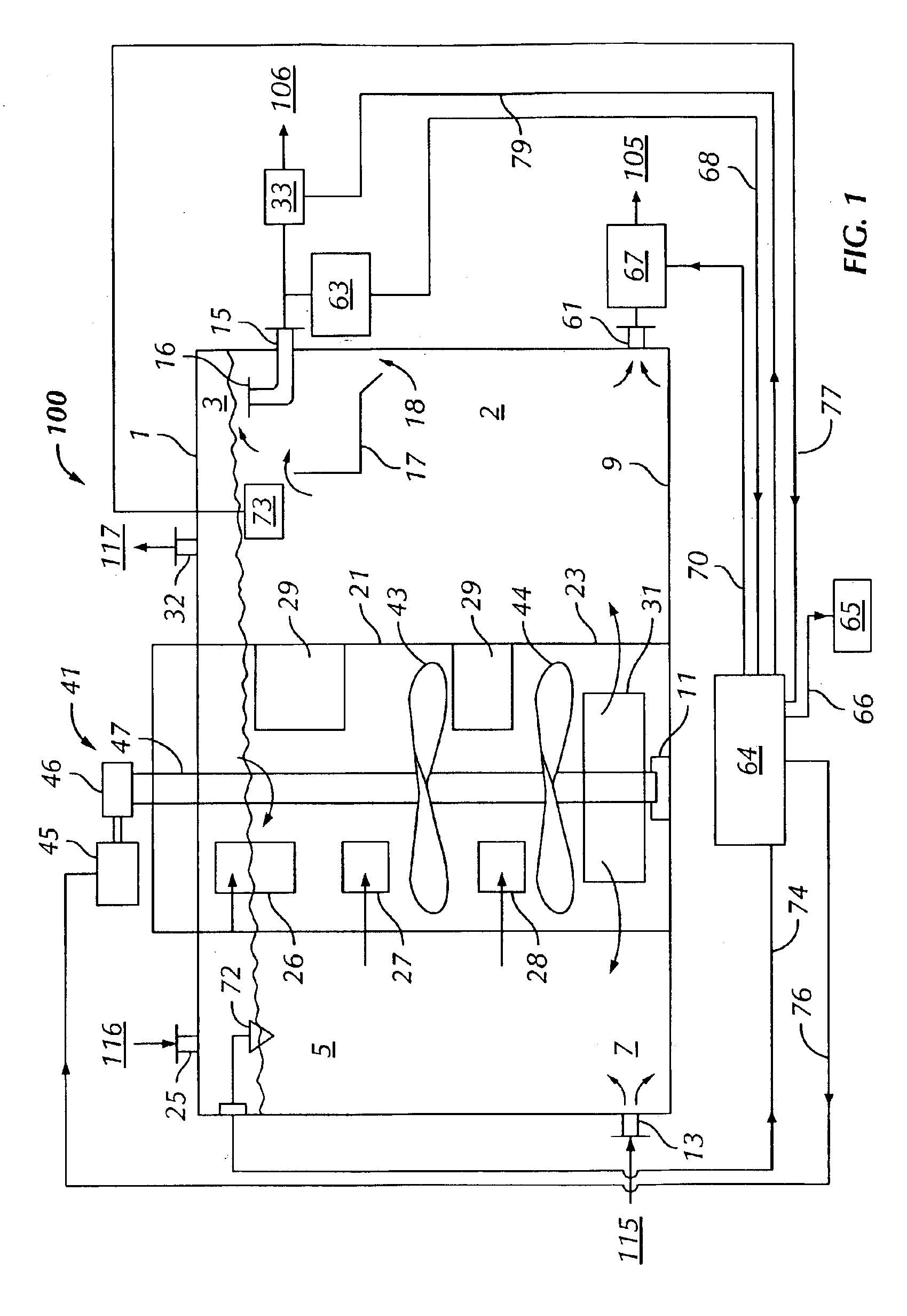
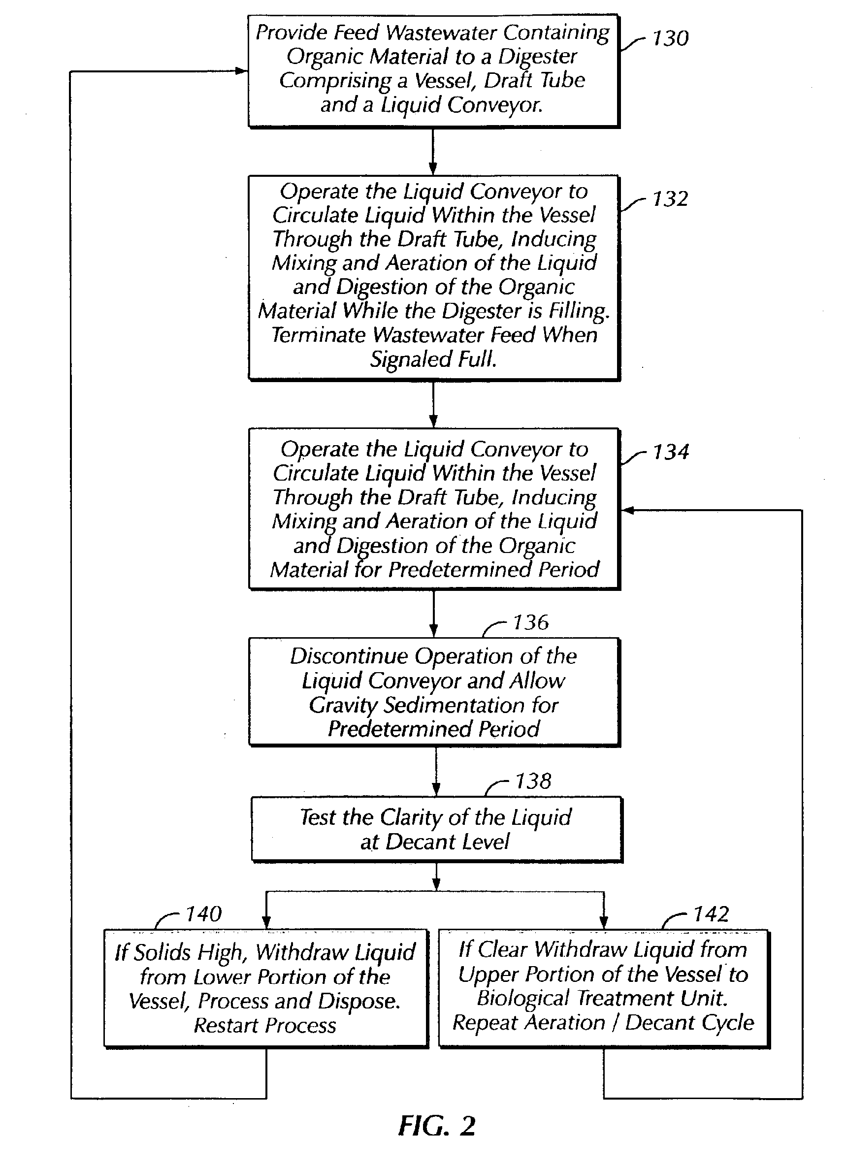
With reference to the figures, the invention relates to an improved aerobic wastewater digester and methods of operating it. Prior aerobic wastewater digesters have the drawbacks that they often yield residual sludge that is relatively non-concentrated and much less thoroughly digested than is theoretically possible. As a result, prior aerobic digesters yielded relatively large amounts of relatively poorly concentrated sludge, resulting in larger sludge disposal costs than can be obtained using the digesters disclosed herein. As described herein, the improved sludge digester can more thoroughly degrade wastewater sludge and concentrate it to a greater degree than previous aerobic sludge digesters, thereby reducing the costs associated with disposal of the sludge and potentially rendering it more amenable for post-digestion sludge processing. In addition, the aerobic sludge digester disclosed herein can be operated under a wider range of conditions than other digesters, including und...


PUM

PropertyMeasurementUnit
Fractionaaaaaaaaaa
Fractionaaaaaaaaaa
Lengthaaaaaaaaaa

Abstract

The invention relates to an aerobic wastewater digestion unit useful for degrading organic material dissolved or suspended in a wastewater stream. The wastewater is fed to a vessel, wherein it is circulated by a liquid conveyor between the vessel and a downwardly-directed tube. Expulsion of fluid from the tube into the lower portion of the vessel agitates the liquid in the vessel and disperses into the liquid air that has been entrained in the liquid in the tube. The digester can be operated using varying liquid levels, and is amenable to batch, semi-batch, and continuous operation. The digester is suitable for use in combination with other components of wastewater treatment systems, and can be included as a module in modular wastewater treatment systems.

Description

BACKGROUND OF THE INVENTIONThe invention relates to treatment of wastewater from residential, business, industrial, or other sources.Wastewaters obtained from various sources can contain bulk solid materials (sticks, rags, sand, and other materials that can be screened or filtered therefrom), smaller suspended solid materials that cannot be easily removed by screening or filtration; organic material, such as fine semi-biodegradable organic solids, soluble organic chemicals, pathogenic microorganisms (e.g., bacteria, viruses, spores, cysts, and protists), undesirable nutrients (e.g., nitrogen- or phosphorous-containing compounds that can encourage nuisance growth of algae or weeds at the wastewater discharge site); and inert solid particles (e.g., grit and sand). Discharge of these materials (many of which exert biological oxygen demand {BOD} when discharged) into the environment with the wastewater can have undesirable health and environmental consequences. As a result, wastewater d...

Claims


Application Information

Patent Timeline
IPC IPC(8): C02F3/12C02F3/00
CPCC02F3/006C02F3/1284C02F2209/42C02F2209/10Y02W10/10
Inventor MCDOWELL, CURTIS S.HANNUM, CHRISMAURER, ROBERT
Owner BRENTWOOD INDS
Why Eureka
Try Eureka