Material and method for three-dimensional modeling

Inactive Publication Date: 2005-03-22
STRATSYS INC
View PDF6 Cites 115 Cited by
  • Summary
  • Abstract
  • Description
  • Claims
  • Application Information

AI Technical Summary

Benefits of technology

The present invention is a thermoplastic material forming a modeling filament comprising a blend of polyphenylsulphone (PPSF) as a major component, and polycarbonate (PC) as a minor component, a method for building a three-dimensional model by layered deposition modeling using the thermoplastic material, and a method for removing supports from a completed model built from the material. A method according to the present invention employs the PPSF/PC blend thermoplastic material as a modeling material for building a three-dimensional model. The PPSF/PC blend thermoplastic material

Problems solved by technology

Building support structures solves the problem of supporting the model, but creates the additional problem of removing the support structure from the finished model without causing damage to the model.
The composite supports are we

Method used


Image

  • Material and method for three-dimensional modeling
  • Material and method for three-dimensional modeling

Examples


example 1

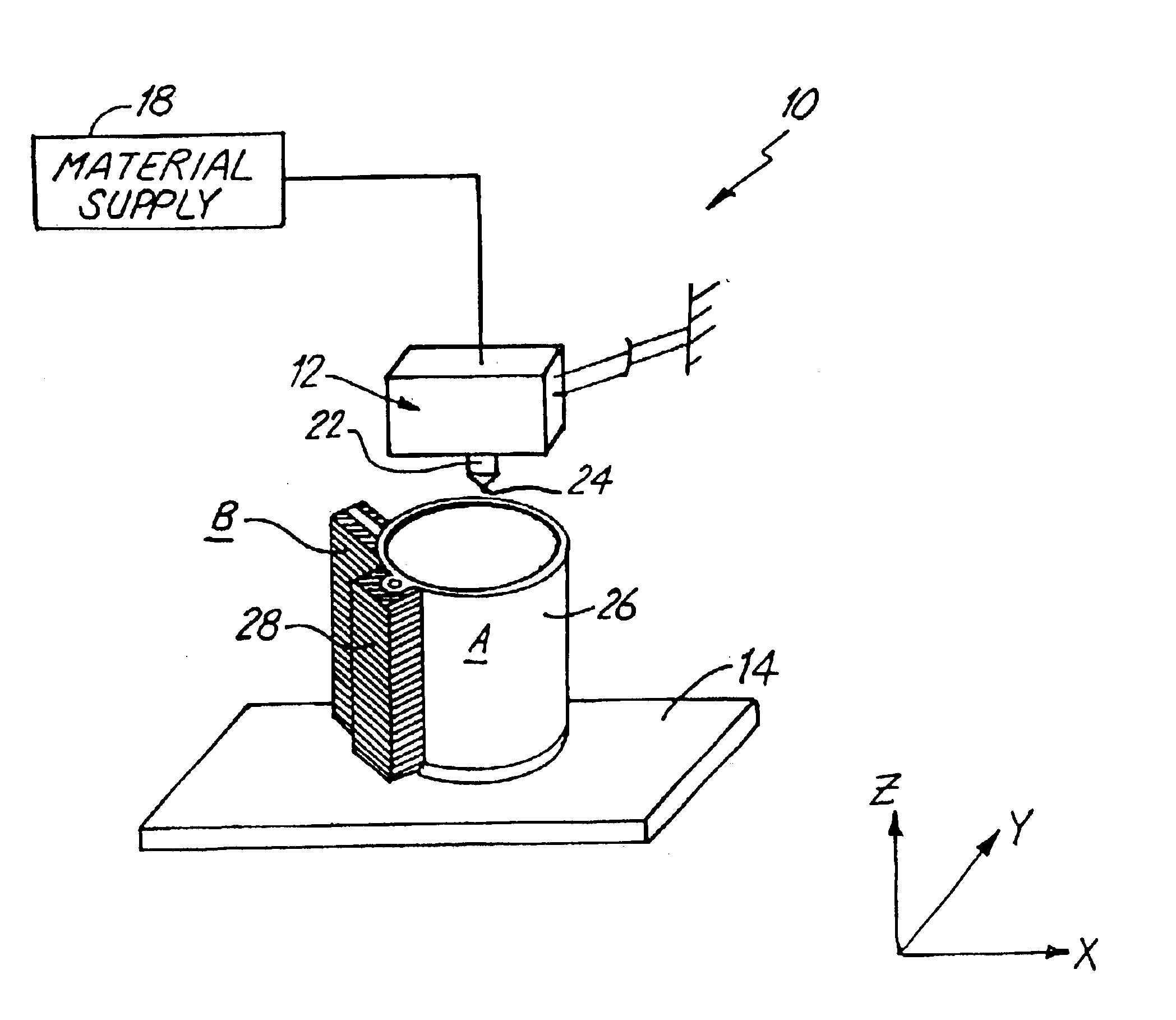
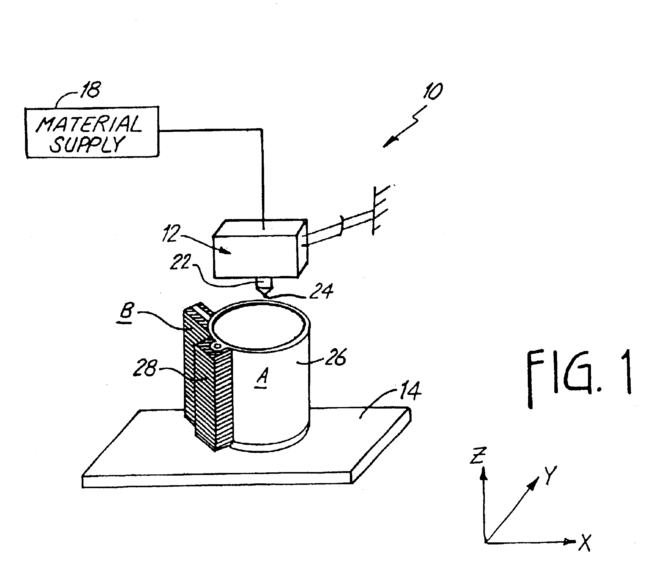
Test models were built in an oven (i.e. build chamber) having a temperature of about 200-225° C., using the polyphenylsulfone modeling material and a support material which comprised various resins of polyethersulfone, polyphenylsulfone or polyetherimide (i.e., Ultem™). These support materials exhibited favorable thermal stability, but could not be broken away from the model. The support material containing polyphenylsulfone adhered very strongly to the model. The support material containing polyetherimide adhered fairy strongly to the model, and the support material containing polyethersulfone, while exhibiting the least adherence to the model, adhered too strongly for suitable use.

Also, the materials of this example exhibited an undesirable build-up in the Liquifier. After extrusion of only about 7 pounds of material, the liquifier needed replacement due to clogging.

example 2

Large and small polyphenylsulfone models were built in an oven having a temperature of about 200-225° C., using a support material comprising a polyethersulfone base polymer and a silicone release agent. For convenience, commercially available compounds were used to provide a “masterbatch” containing silicone, which was compounded with the base polymer. Various masterbatches were tested, which included polypropylene, linear low-density polyethylene, and high-impact polystyrene. Additionally, various silicones were tested, ranging in viscosity from about 60,000 centistokes (intermediate viscosity) to 50 million centistokes (very high viscosity). The very high viscosity silicones have a high molecular weight, while the lower viscosity silicones have a lower molecular weight.

It was found that intermediate viscosity silicone was a much better release agent than the very high viscosity silicone, and that the high-impact polystyrene masterbatch released more easily from the polyphenylsulf...

example 3

Large and small polyphenylsulfone models were built in an oven having a temperature of about 200-230° C., using the support material consisting of polyethersulfone, high-impact polystyrene and a silicone release agent, as described in Example 2. In this example, silicone was added to the PPSF resin as well. Various concentrations of silicone were tested, up to about 5 weight percent silicone, using various masterbatches.

It was found that the silicone additive marginally increased liquifier life, from about 7 pounds of extruded modeling material to about 10 pounds. The silicone additive likewise marginally improved releasability of the model from its support structure.


PUM

PropertyMeasurementUnit
Temperatureaaaaaaaaaa

Abstract

The present invention is a modeling technique wherein a three-dimensional model and its support structure are built by fused deposition modeling, using a thermoplastic blended material containing a polyphenylsulfone (PPSF) polymer and a polycarbonate (PC) polymer to form the model. The PPSF/PC blend exhibits good chemical resistance, thermal stability, and resists build-up in the nozzle of a three-dimensional modeling apparatus. Removal of the support structure from a completed model is facilitated by operating on the material while it is hot.

Description

CROSS-REFERENCE TO RELATED APPLICATION(S)None.BACKGROUND OF THE INVENTIONThis invention relates to the fabrication of three-dimensional objects using additive process modeling techniques. More particularly, the invention relates to forming three-dimensional objects by depositing a first solidifiable material in a predetermined pattern so as to form a three-dimensional object, in coordination with the depositing of a second solidifiable material so as to provide a support structure for the three-dimensional object as it is being built.Additive process modeling machines make three-dimensional models by building up a modeling medium, based upon design data provided from a computer aided design (CAD) system. Three-dimensional models are used for functions including aesthetic judgments, proofing the mathematical CAD model, forming hard tooling, studying interference and space allocation, and testing functionality. One technique is to deposit solidifiable modeling material in a predetermi...

Claims


Application Information

Patent Timeline
IPC IPC(8): B29C41/02B29C41/42B29C41/34B29C71/02C08F283/02C08F283/00C08L81/00C08L81/06C08L69/00H05B6/64B29C48/92B29C67/00
CPCB29C67/0055B29C67/0092B29C47/92B29C71/04B29K2069/00B29C2035/0855B29K2081/06B29C64/40B33Y70/00B33Y30/00B33Y10/00B29C64/118B29C64/106
Inventor HOPKINS, PAUL E.
Owner STRATSYS INC
Why Eureka
Try Eureka